ROS Control combines a set of packages that include controller interfaces, controller managers, transmissions and hardware_interfaces. The ROS control framework is used to implement and manage robot controllers for real robots and in simulation within gazebo.
Big Picture and Goals
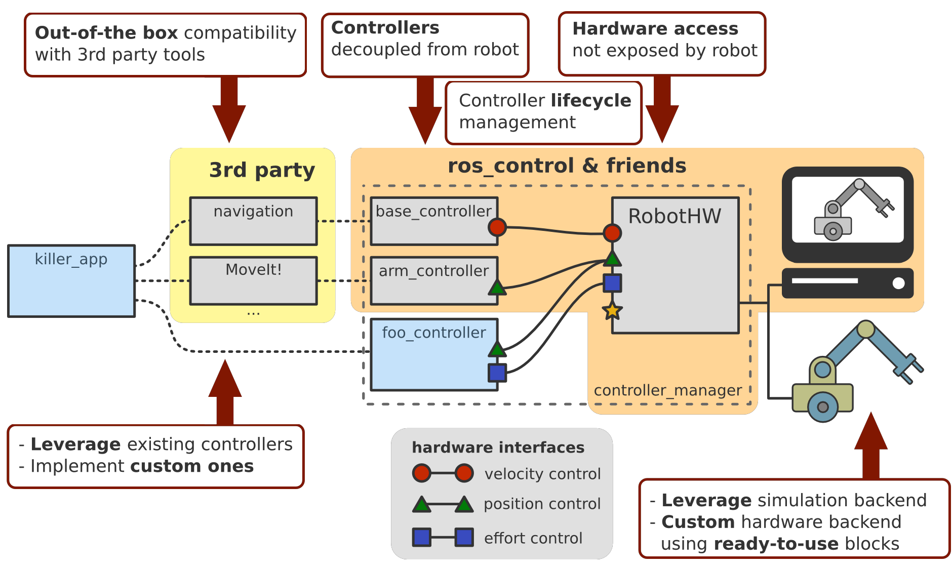
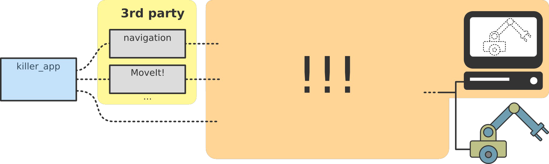
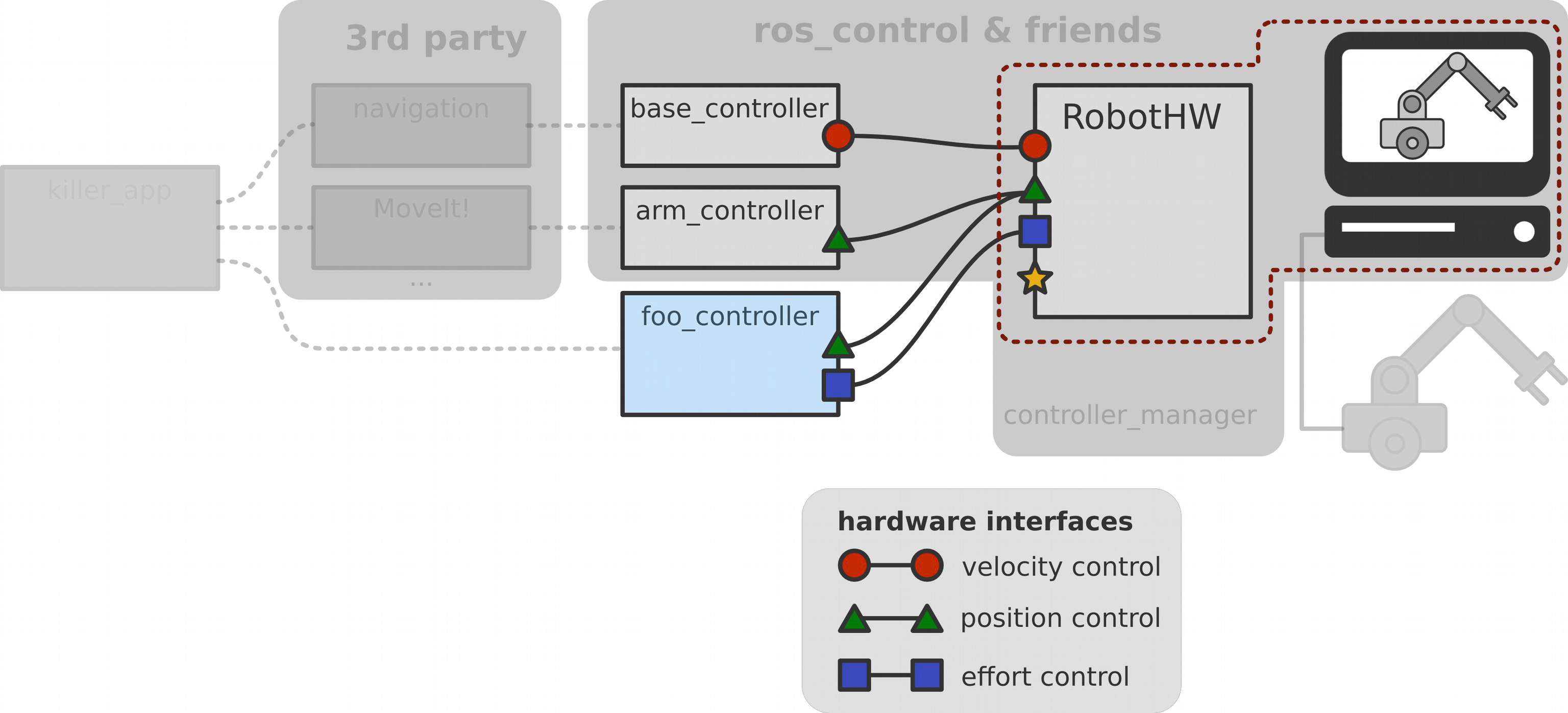
Let’s start with a typical scenario: you have a robot, or even more general, a piece of hardware, and you would like to run an application that leverages ROS specific libraries like MovieIt! or the navigation stack. All these libraries are well tested and you don’t want to rewrite them. On the other hand you probably have a computer that is running a simulator like Gazebo to simulate your robot. To make ends meet we can make use of the ROS control project.
ROS control helps you writing controllers including real-time constraints, transmissions and joint limits.
It provides tools for modeling the robot in software, represented by the robot hardware interface (hardware_interface::RobotHW), and comes
with ready to use out of the box controllers, thanks to a common interface (controller_interface::ControllerBase) for different applications which then talk to third-party tools.
The important aspects to highlight is that the hardware access to the robot is decoupled, so you don’t expose how you talk to your robot. This means that controllers and your robot hardware structure are decoupled so you can develop them independently and in isolation which enables you to share and mix and match controllers.
When you want to write your robot backend, there’s a possibility to leverage an out of the box simulation backend (gazebo_ros_control plugin).
After you’ve tested your robot in simulation, and want to work on the real robot hardware, you will want to write your custom hardware backend for your robot. For this, there are also tools that help making this task easier for you.
There is already a set of existing controllers (see the ros_controllers meta package) that are robot agnostic, which should hopefully enable you to leverage some of those. However, if your application requires it, then there are tools (controller_interface) that help you also implement custom controllers. ROS control also provides the controller manager for controlling the life cycle of your controllers.
When it comes to third party libraries, there is out of the box compatibility with general purpose robot tools like visualization, tf and rqt plugins. The project provides also compatibility with the navigation stack for differential drive robots and biped humanoid robots and it also enables motion planning with MoveIt.
The whole idea is that what you can focus on your actual application or research paper and not have to bother writing the boiler plate code to get everything working with your robot hardware.
Another important aspect is that ROS control is real-time ready in the sense that if your application has (hard) real-time constraints then you can use ROS control with it. However, if your application doesn’t have real-time constraints then it is not imposed on you. Also the choice of using a real-time operating system is entirely up to you.
In a nutshell, the goals of the project are to
- lower the entry barrier for exposing hardware to ROS.
- promote the reuse of control code in the same spirit that ROS has done for non-control code, at least non-real-time control code.
- provide a set of ready-to-use tools.
- have a real-time ready implementation.
History
By the year 2009 there was the pr2_controller_manager that was developed by Willow Garage which was specific for the pr2 robot. This changed in the late 2012, where hiDOF in collaboration with Willow Garage started the ROS control project which by early 2013 was continued by PAL robotics and community efforts. ROS control is basically a robot agnostic version of the pr2_controller_manager.
Related Work
There’s quite a few component-based frameworks like Orocos RTT (and also there’s a couple of projects that build upon Orocos RTT as well), openRTM, Yarp. For computational graph models there’s Ecto there’s Microblx, and many non-robotics implementations, especially within the audio and graphics communities.
Without ROS control there would be no end-to-end solution for ROS users. ROS control tries to bring standard ROS interfaces (topics, services, actions) closer to the hardware and therefore to push the integration effort to the driver level, the rightmost part of the overview image.
Ros Control and its Repositories
The ROS control project consists of a github organization that’s called ros controls.
There you find messages and action definitions, tools that help you writing real-time code (realtime_tools) in the context of control, hardware interfaces (hardware_interface and the transmission_interface package to describe your robot and the controller_manager. The core framework is found in the ros_control package which is compatible with ros_controllers that provides a set of robot agnostic controllers.
The ros_control meta package is composed of the following individual packages:
control_toolbox: This package contains common modules (PID and Sine) that can be used by all controllers.controller_interface: This package contains the interface base class for existing controllers and to develop new ones that will work with the ROS control framework.controller_manager: This package provides the infrastructure to load, unload, start, and stop controllers.controller_manager_msgs: This package provides the message and service definitions for the controller manager.hardware_interface: This contains the base class for the hardware interfacestransmission_interface: This package contains the interface classes to model transmissions (simple reducers, differentials or four-bar linkages)
Setting up a Robot
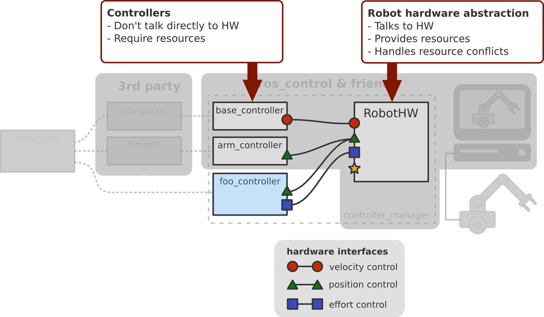
ROS control is split into two parts. First there is the robot hardware abstraction, which is used to communicate with the hardware. It provides resources like joints and it also handles resource conflicts. On the other hand, we have controllers. They talk to the hardware through the hardware interface and they require resources that are provided by the hardware abstraction.
Hardware Abstraction and Controllers
Let’s get a more detailed view of the hardware abstraction and the communication between and with ROS controllers.
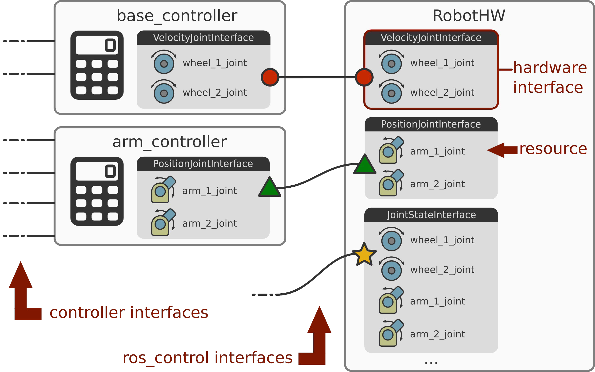
The hardware interface is a software representation of the robot and its abstract hardware.
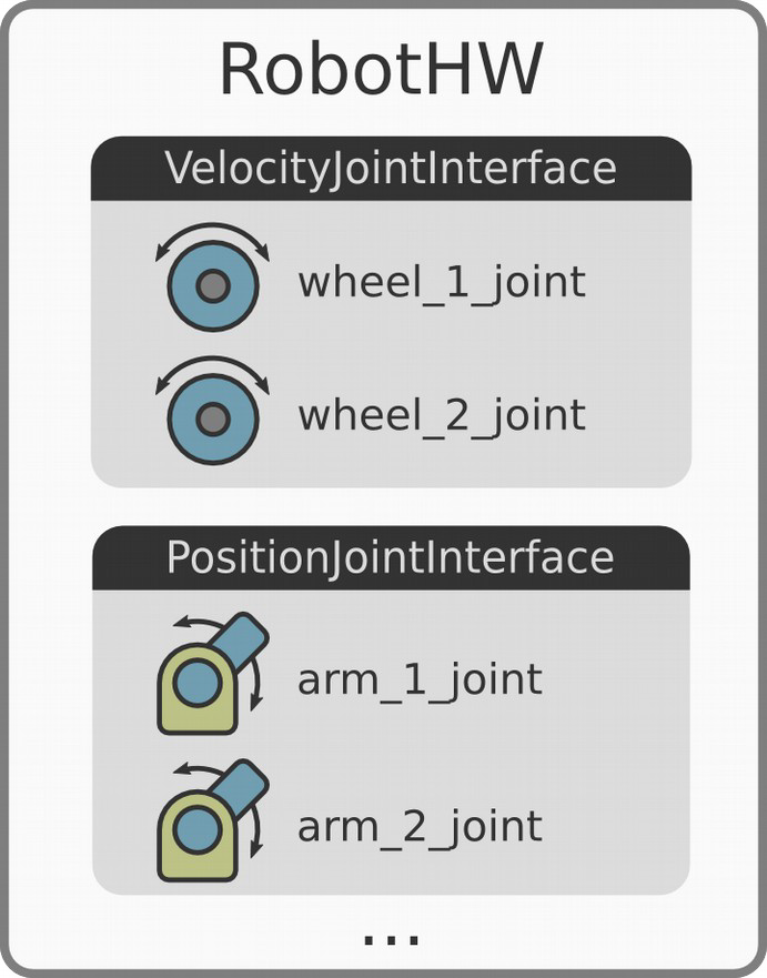
In ROS control speak, we have the notion of resources, which are actuators, joints and sensors.
Some resources are are read-only, such as joint states, IMU, force-torque sensors, and so on, and some are read and write compatible, such as position, velocity, and effort joints.
A bunch of hardware interfaces, where one is just a set of similar resources, represent a robot.
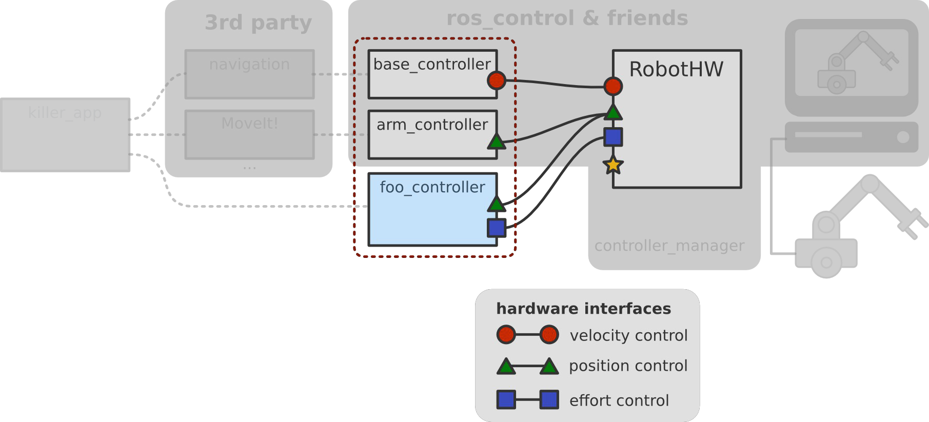
The robot hardware, represented in software, and the controllers are connected via ROS control’s interfaces, not to be confused with typical ROS interfaces like topics, actions or services. This means, we are just passing pointers around which is real-time safe. The interfaces of the robot hardware are used by controllers to connect and communicate with the hardware. At the leftmost part of the image we see that controllers have their interfaces, which are typically ROS interfaces (topics, services or actions) that are custom so your controller can expose whatever it wants.
Exclusive Resource Ownwership
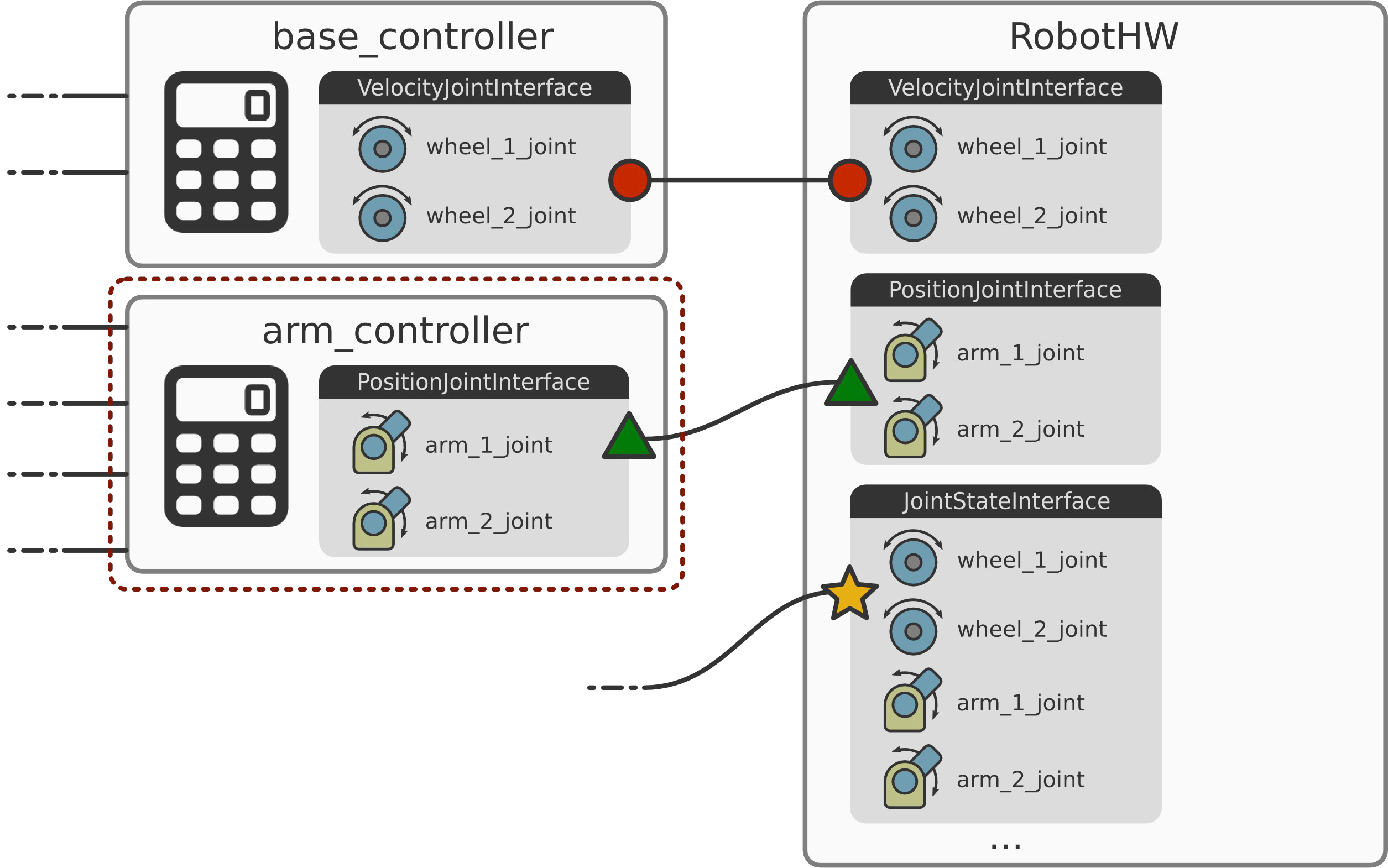
You can have multiple controllers accessing the same interface. In the image below you can see that the two arm controllers both use the first arm joint.
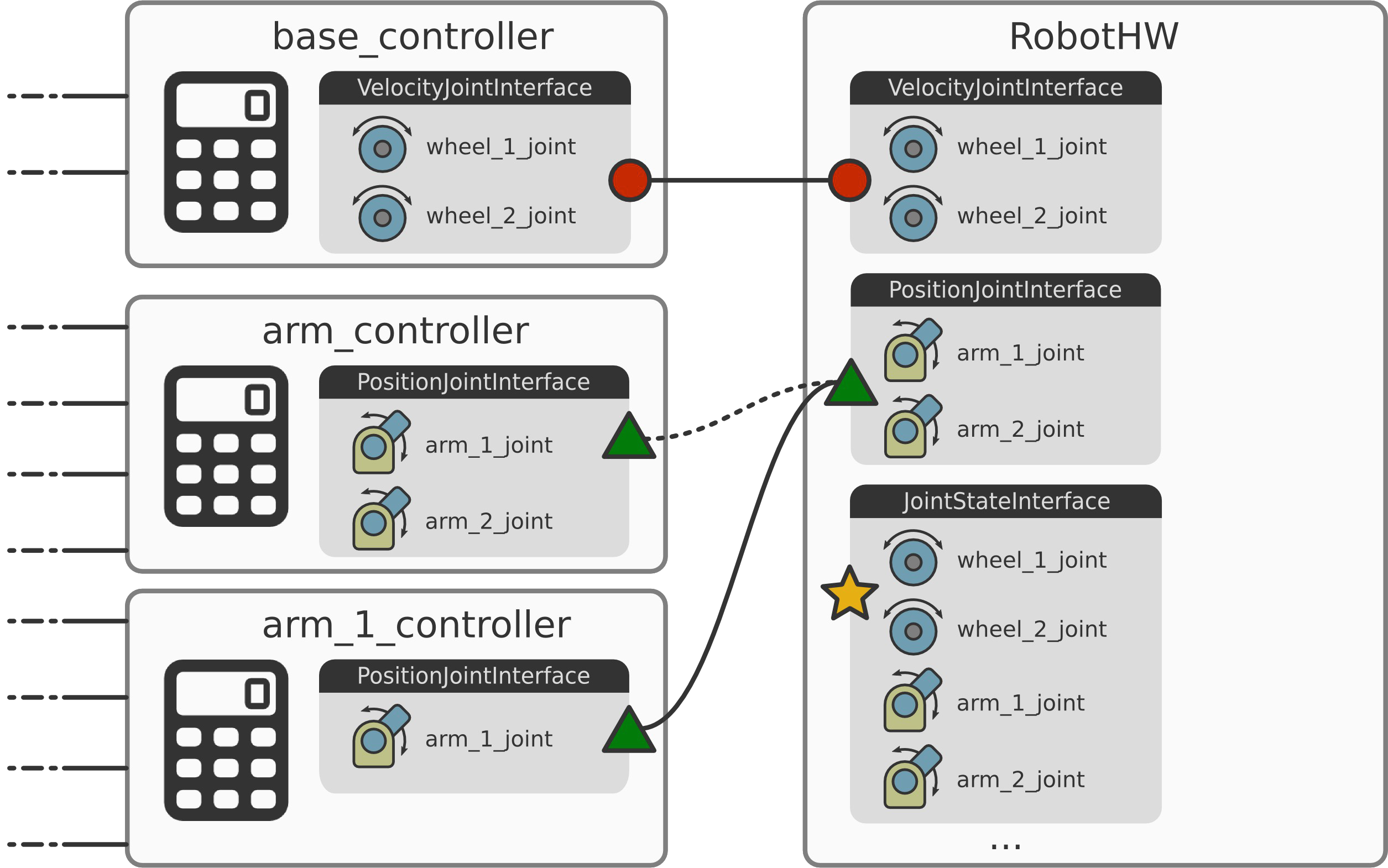
By default there’s a policy of exclusive resource ownership. In this case, you can either have one or the other but not both controllers running at the same time, which is enforced by ROS control. If you want other policies, you can implement them as well.
Memory Layout
Now we will learn how the hardware interface actually communicates with the real or simulated hardware using doubles and floats which represent the actual data that you want to pass around.
The following image depicts the memory layout of your raw data and you can see the memory regions where you actually read and write from and to hardware.
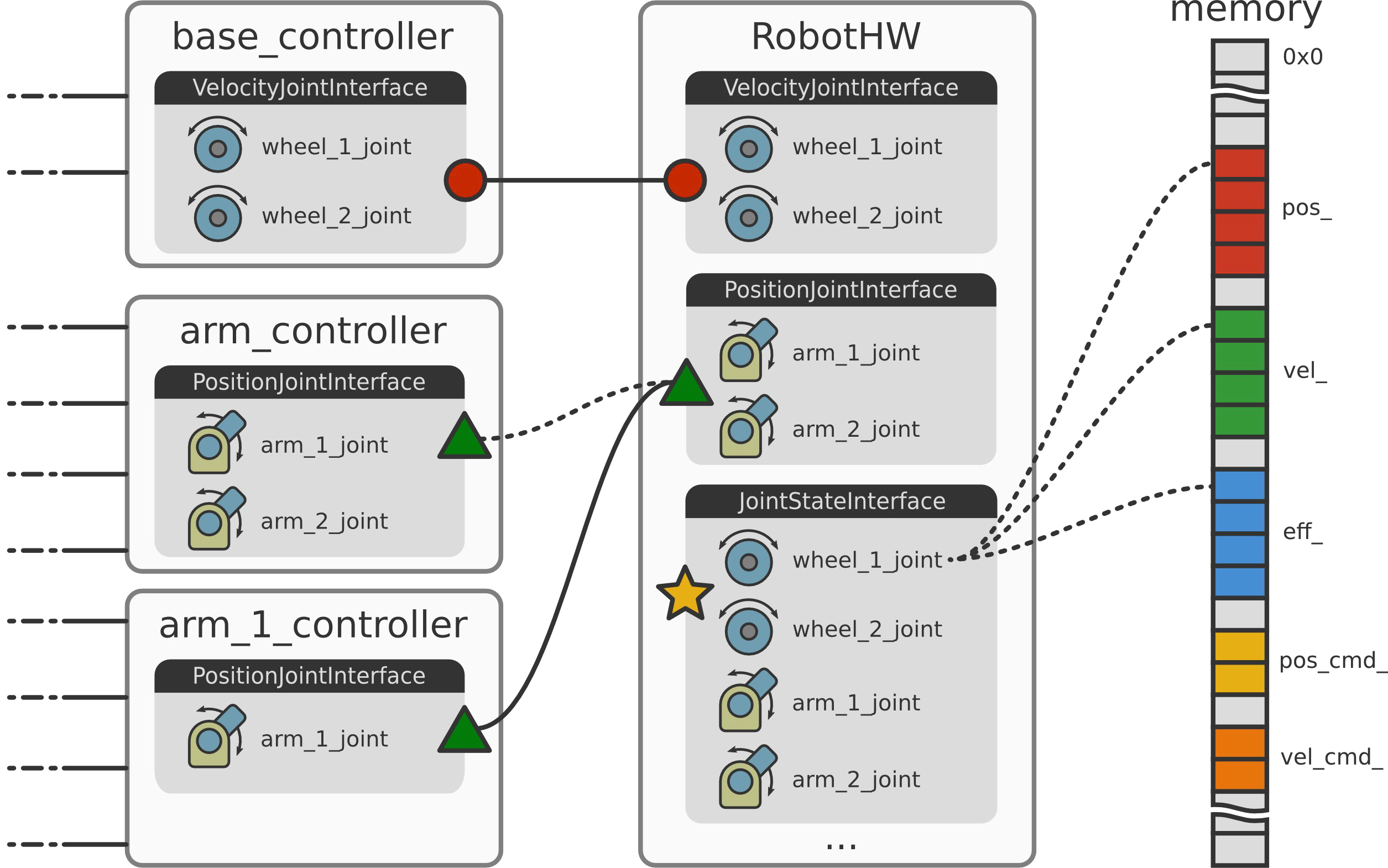
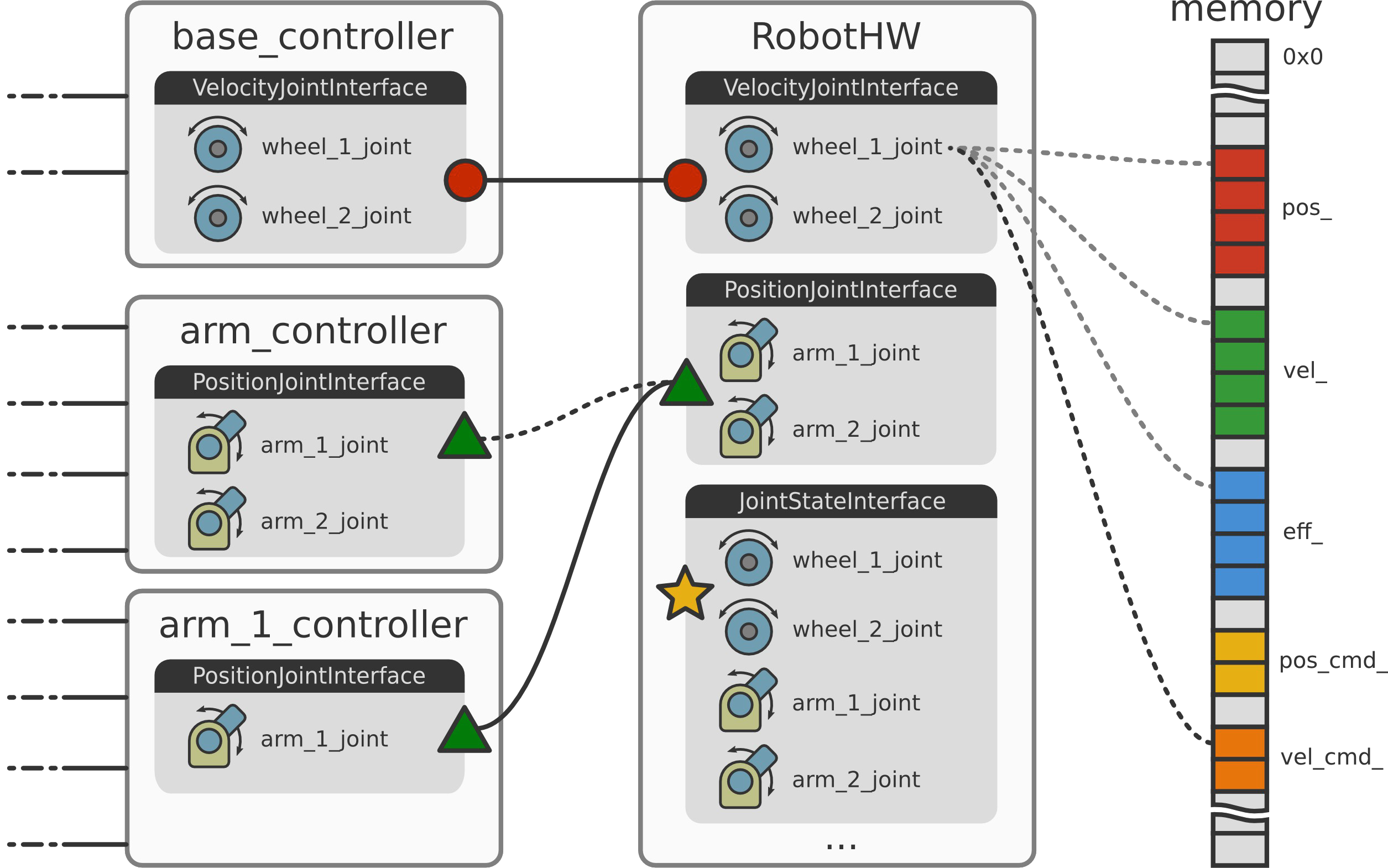
A resource is nothing else than pointers to the raw data that adds some semantics to the data such as describing that it is a position or velocity, the name of the joint and that it belongs for example to a joint state interface.
As you see in the memory layout image above, joint state interfaces are used for reading joint state.
If you have a resource that can receive commands and at the same time provide feedback you can use the joint command interface. This interface is the base interface for other joint interfaces for position, velocity and effort (see the C++ hardware_interface API).
These interfaces provide semantic meaning which allow you to read the joint state and also send semantically meaningful commands.
The following is a simple code example.
#include <hardware_interface/robot_hw.h>

class MyRobot :
    public hardware_interface::RobotHW
{
public:
    MyRobot(); // Setup robot
    MyRobot(ros::NodeHandle &nh, urdf::Model *urdf_model = NULL);

    // Talk to HW
    void read();
    void write();


    // Requirement only if needed ...
    virtual bool checkForConflict(...) const;
}
To implement your custom robot hardware interface you inherit from a class called hardware_interface::RobotHW that is part of ROS control. In the constructor you set up your robot, either implemented in code (see for example: eborghi10/my_ROS_mobile_robot) or using a robot description in the form of an urdf model. The latter requires that you pass the urdf model to the constructor or load it from the parameter server. An example using the urdf description can be found in the ros_control_boilerpalte repository.
After the robot setup we need to implement the read() and write() methods, which is robot specific and up to you to implement. The read() method is used to populate the raw data with your robot’s state. write() is used to send out
raw commands via CAN bus, Ethernet, Ethercat, serial port or whatever protocol your robot hardware uses.
Within the ROS community, there are some projects that can help you out with this. Examples are ROS-Industrial, rosserial, SR Ronex and other custom solutions out there that you can leverage.
In case exclusive resource ownership is not good enough, you can always reimplement the virtual member function hardware_interface::RobotHW::checkForConflicts() with your custom implementation.
In summary, the package called hardware_interface (see also its C++ API) provides all the building blocks for constructing a robot hardware abstraction. It is the software representation of your robot and the idea is to abstract hardware away which is done using resources (actuators, joints and sensors), interfaces, that are sets of similar resources, and make up a robot, which is a set of interfaces. The hardware interface also handles resource conflicts and by default we have exclusive resource ownership.
Out of the box ROS control provides resources and interfaces to read states such as joint state (position, velocity and effort) IMU and force-torque sensors. If, in addition to reading, you also want to send commands there are interfaces for position control joints, but also velocity and effort control joints. For a list of all available interfaces check out the Hardware Interfaces section on the ros_control wiki page.
Similar interfaces exist for actuators, which will be explained later.
Simulation Backend
To simulate your robot there is a package called gazebo_ros_control which is located outside the ROS control organization repositories in ros-simulation/gazebo_ros_pkgs. It is a Gazebo plugin for ROS control.
There exists a default plugin, which populates all the joint interfaces from the URDF by parsing transmission specification and optionally joint limits, which will be describe later in the post. If you use the default plugin and want your
robot to show up in your Gazebo simulator, the following is all you have to add to your urdf description, apart from the robot’s transmissions.
<gazebo>
  <plugin name="gazebo_ros_control" filename="libgazebo_ros_control.so">
    <robotNamespace>/my_robot</robotNamespace>
  </plugin>
</gazebo>
This makes it simple to test ROS control because we don’t have to write any robot hardware interface code. Instead, we just need to setup some configuration files.
There’s also a custom plugin where most of the details are up to you. TODO source?
Controllers
In the following images we concentrate on the controllers
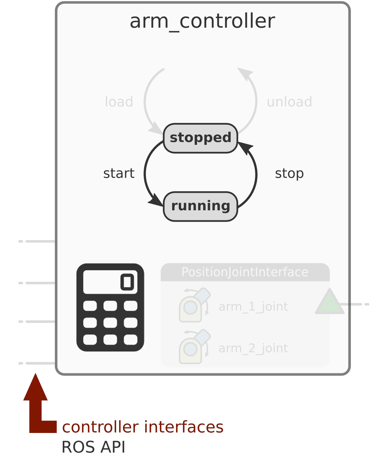
and see more of the arm controller’s internals.
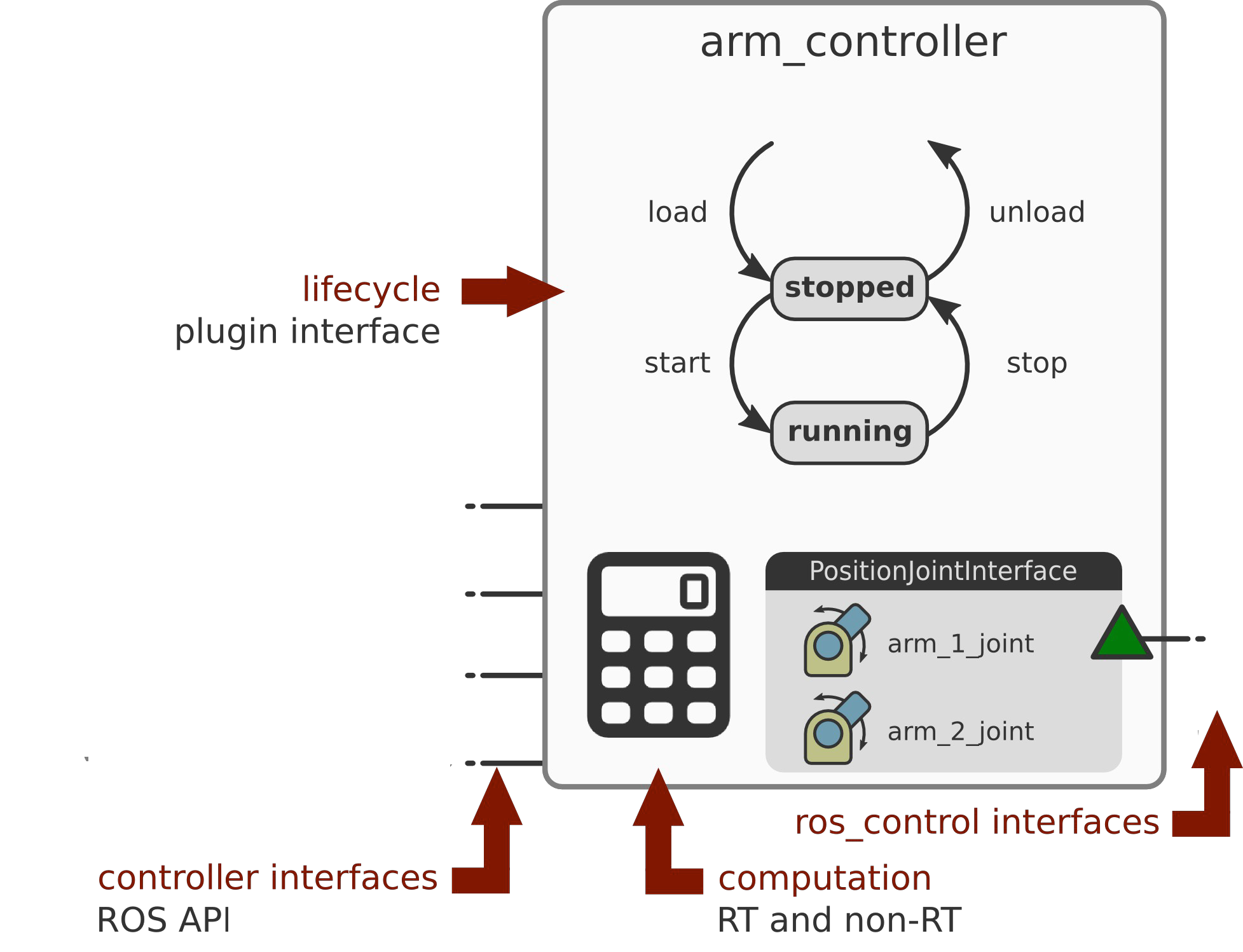
As mentioned, a controller requires resources in the form of ros_control hardware interfaces (located on the right side in the image). On the left hand side we have the controller’s ROS API.
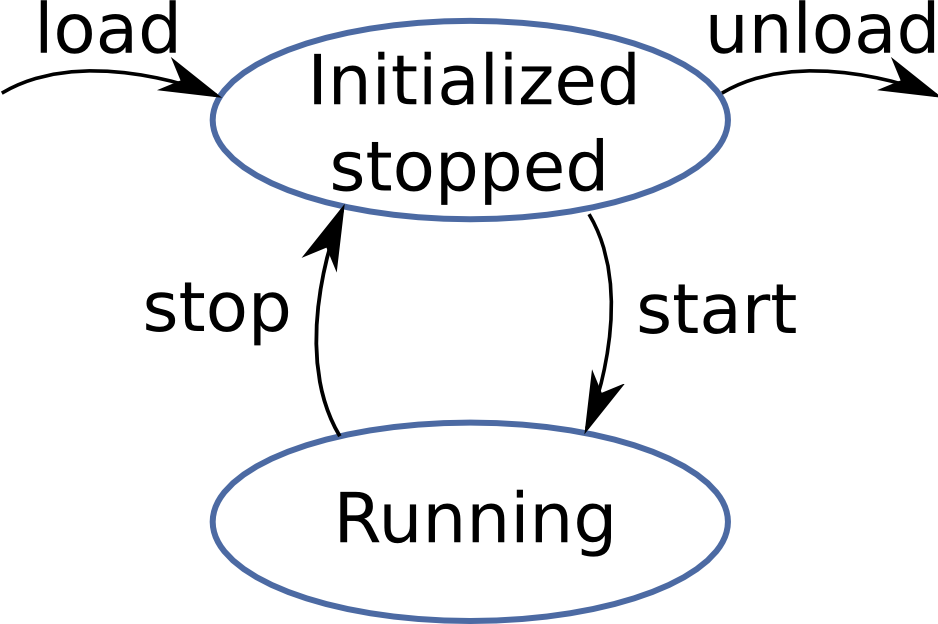
Controllers use a plugin interface that implements the controller lifecycle. The lifecycle is a simple state machine with transitions between two states which are “stopped” and “running”. A controller has two computation units where one is real-time safe and the other is non real-time.
The state machine uses non real-time operations to load and unload a controller.
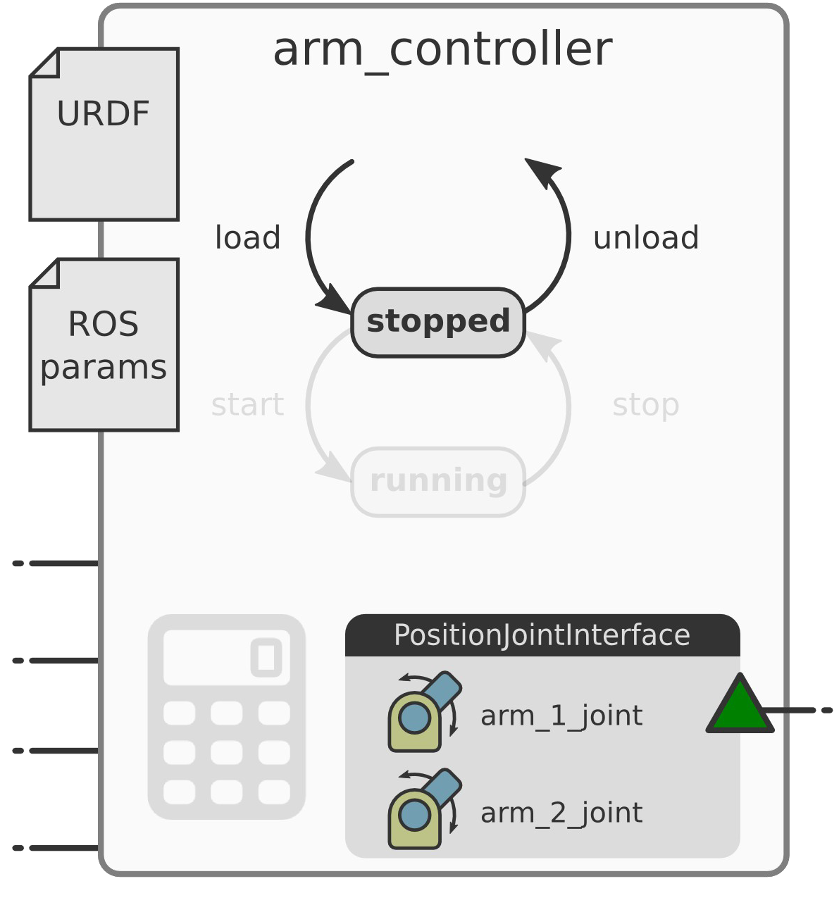
Loading controller is done by the controller_manager which initializes the controller plugin defined in a config yaml file and checks requisites, for example the existence of hardware resources
(note that this is not the same as hardware resource conflict handling). In the arm controller example,
we need two joints named arm_1_joint and arm_2_joint and they must implement the PositionJointInterface.
In case your robot doesn’t have that interface with the resources, the controller you want to use cannot work with that robot. You can also check for things like the robot URDF description configuration or a controller specific configuration like ROS parameters scoped within the controller namespace. Finally in the load method you setup the ROS interfaces which define how your clients will talk to the controller.
The steps to unload a controller plugin are implemented in the destructor of the controller.
ROS control has real-time safe operations, for transitioning between the stopped and running states.
When you start() the controller the following is what gets executed before the first controller update():
- Resource conflict handling (different from resources existence: by this time we know that resources exists but we check if the resource is already in use or available for your controller (in the case of exclusive ownership)
- The next typical policy is to apply what’s called semantic zero. This means, after the controller starts you would for example hold the position, set the velocity to zero, activate gravity compensation or something else that makes sense in your use case.
The stop() operation goes from the “running” to the “stop” state. The typical policy for this operation is to cancle goals.
Cancelling all goals avoids a rapid movement the next time you start your controller because it doesn’t try to resume what it was doing the last time around.
The last real-time safe operation is update() which is a real-time safe computation, if implemented accordingly. This means you have to take care the implementation of update() is actually real-time safe, or if you don’t have real-time constrains, that the implementation is deterministic.
The updated() method is executed periodically in the “running” state.
Finally, the last part of computations that exist in controllers are non real-time operations which are executed asynchronously and take place in the callbacks of your controller’s ROS interface.
In summary, controllers are dynamically loadable plugins that have an interface which defines a very simple state machine. This interface clearly separates the operations that are non real-time safe from those that are required to be real-time safe. Finally, the computation can take place in the controller update, which in this case is both periodic and real-time safe, and we have computation in the ROS API callbacks, which is asynchronous and non real-time safe.
Controller Toolbox
To write your own controllers there is a helpful package controller_toolbox which contains tools useful for writing
controllers or robot abstractions.
The following is a list of tools you can use:
- Pid PID loop
- SineSweep for joint frequency analysis
- Dither white noise generator
- LimitedProxy for convergence without overshoot
- …
ROS Controllers
Another helpful repository is ros_controllers which provides ready to use out of the box controllers.
If you plan to develop a controller, you should first check in this repository if it already exists.
This repository has three controllers for reporting the joint state from sensors:
joint_state_controllerreads joint states and publishes it to the/joint_statetopic of typesensor_msgs/JointState. Note: although it contains the word controller in its name, it is not actually controlling anything. However, it should always be used to publish the current joint states for other nodes such astf. It is also worth mentioning that it should not be confused withjoint_state_publisher(see this answer for a distinction).imu_sensor_controllerpublishessensor_msgs/Imutopics.force_torque_sensor_controllerpublishesgeometry_msgs/Wrenchtopics.
It also provides multiple general purpose controllers. There are three packages that implement simple single joint controllers that operate in different control spaces (position, velocity and effort). These main ROS controllers are grouped according to the commands that get passed to your hardware/simulator:
effort_controllers: used when you want to send commands to an effort interface. This means that the joints you want to control accept an effort command.joint_effort_controllerwith this subclass theeffort_controllersplugin accepts effort set values as input.joint_position_controllerwith this subclass theeffort_controllersplugin accepts position set values as input.joint_velocity_controllerwith this subclass theeffort_controllersplugin accepts velocity set values as input.
position_controllers: used when you want to send commands to a position interface. This means that the joints you want to control accept a position command.joint_position_controllerwith this subclass theposition_controllersplugin accepts only position set values as input.joint_group_position_controller
velocity_controllers: used when you want to send commands to a position interface. This means that the joints you want to control accept a velocity command.joint_velocity_controllerwith this subclass theposition_controllersplugin accepts only velocity set values as input.joint_group_velocity_controller
To set an entire trajectory, the following controllers are defined:
joint_trajectory_controllersis mostly used for manipulation and implements the action interface that is expected by MoveIt! in the default ROS bindings. The controller accepts commands as either actions of typecontrol_msgs/FollowJointTrajectoryor via the topictrajectory_msgs/JointTrajectory.position_controllervelocity_controllereffort_controllerposition_velocity_controllerposition_velocity_acceleration_controller
For navigation there is the diff_drive_controller which accepts commands in the form of geometry_msgs/Twist topics and publishes odometry to tf and nav_msgs/Odometry. It exposes a ROS interface that is compatible with the ROS navigation stack.
For manipulation we can use the gripper_action_controller which implements a single-DOF gripper controller.
It accepts commands as actions of type control_msgs/GripperCommandAction and is compatible with MoveIt!.
Controller Lifecycle Management
To bring the robot hardware abstraction and the controllers together ROS control uses the controller manager
which lives in a package with the same controller_manager and takes care of the control loop.
Controller Manager

The controller manager knows about the robot and the controllers. Its two main purposes are: robot resource management and controller lifecycle management.
The controller manager knows about resources and can therefore enforce the resource conflict policy, for example, exclusive ownership.
It also takes care of controller lifecycle management. Because the controller_manager knows about the controllers
it handles the transitions of the controller state machine and it also updates the running controllers.
It is important to mention that, by design, controller updates are serialized in a single thread and they are periodic.
The controller manager has an API which is based on ROS services. This API is used for
- Controller lifecycle managment: to transition between the states of the controller state machine
load_controllerunload_controllerswitch_controller: Note that there are no separate start and stop services. Instead, there is a service that is called switch. With that, it is possible to to stop a set of controllers and then start a set of controllers in the same control cycle. This might be relevant if you have a robot arm that is stopped hanging in mid air and you want to change control strategies. What might happen in this case is that your arm falls down when a few control cycles pass. With the switch service you can guarantee that there is no control cycle without any controller running unless that is what you want.
- Query services:
list_controllers: list the currently running controllers or which controllers are available for loading.list_controller_types:
- Other services useful for debugging
reload_controller_libraries
The Control Loop
The following image shows the control loop in its most basic and simplified form:
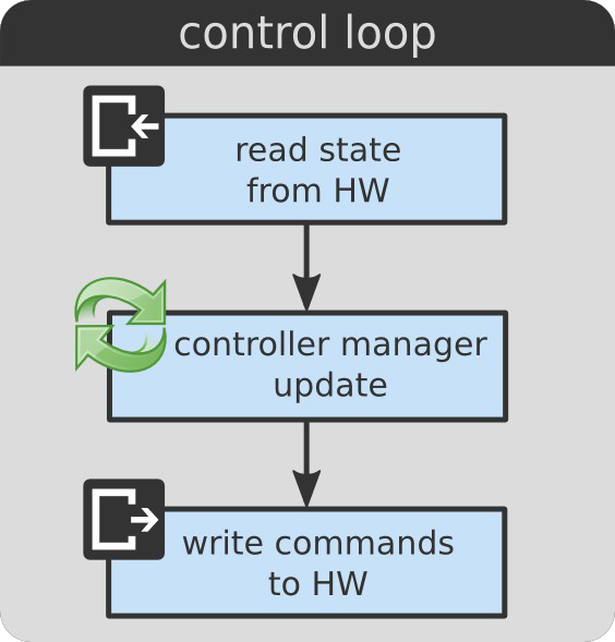
Typically, you first read the state from the hardware through the hardware interface, then use the controller manager to update the controllers with the current hardware state, and finally you send the commands from the update step back out to the hardware.
#include <ros/ros.h>
#include <my_robot/my_robot.h>
#include <controller_manager/controller_manager.h>

int main(int argc, char **argv)
{
    // Setup
    ros::init(argc, argv, "my_robot");

    MyRobot::MyRobot robot;
    controller_manager::ControllerManager cm(&robot);

    ros:AsyncSpinner spinner(1);
    spinner.start();

    // Control loop
    ros::Time prev_time = ros::Time::now();
    ros::Rate rate(10.0); // 10 Hz rate

    while (ros::ok())
    {
        const ros::Time     time   = ros:Time::now();
        const ros::Duration period = time - prev_time;

        robot.read();
        cm.update(time, period);
        root.write();

        rate.sleep();
    }
    return 0;
}
Let’s step through the code snippet:
We first initialize our ROS node:
// Setup
ros::init(argc, argv, "my_robot");
Create an instance of your robot so that this instance knows about all the resources that are available (remember the hardware_interface). Next we create an instance of the controller manager and pass it the robot, so that it can handle its resources:
MyRobot::MyRobot robot;
controller_manager::ControllerManager cm(&robot);
Next, we setup a separate thread that will be used to service ROS callbacks:
ros:AsyncSpinner spinner(1);
spinner.start();
The following snippes show the actual control loop. First we setup the period of the control loop, which in this case is slow (non real-time) 10 Hz.
// Control loop
ros::Time prev_time = ros::Time::now();
ros::Rate rate(10.0); // 10 Hz rate
Inside the while loop we do some basic bookkeeping to get the system time in order to compute the control period:
const ros::Time     time   = ros:Time::now();
const ros::Duration period = time - prev_time;
And then the actual control loop (read, update, write) begins executing:
robot.read();
cm.update(time, period);
root.write();
All these steps keep getting repeated with the specified rate:
rate.sleep();
The read, update and write operations take place in a thread, which is called the control thread:
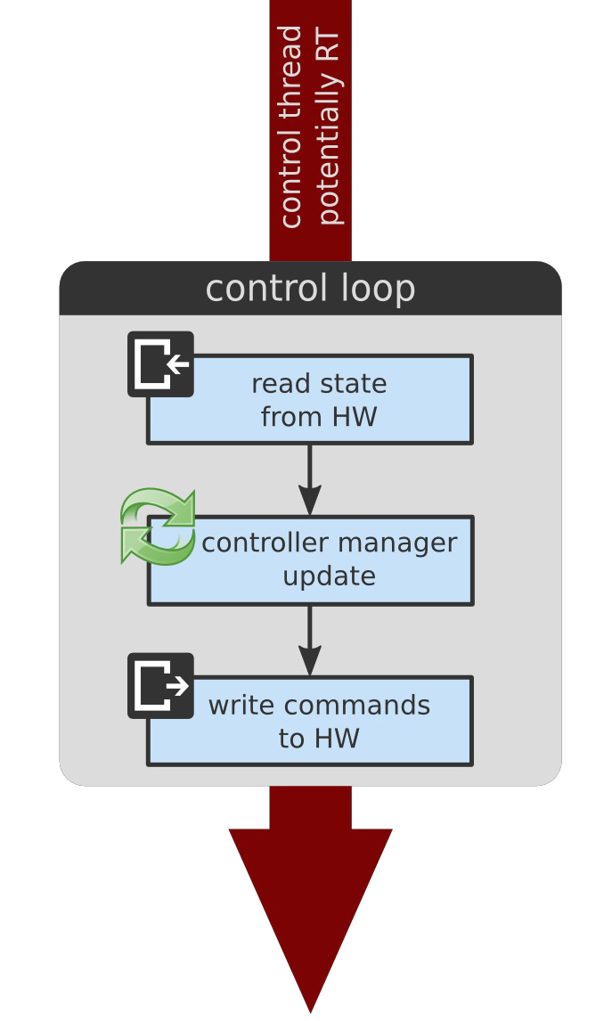
This thread potentially operates in real-time. If your system has real-time contraints, then it is this part of the code (read, update, write) where you should make sure it has real-time scheduling.
There is another non real-time thread, called the spinner thread, that is responsible for servicing ROS callbacks.
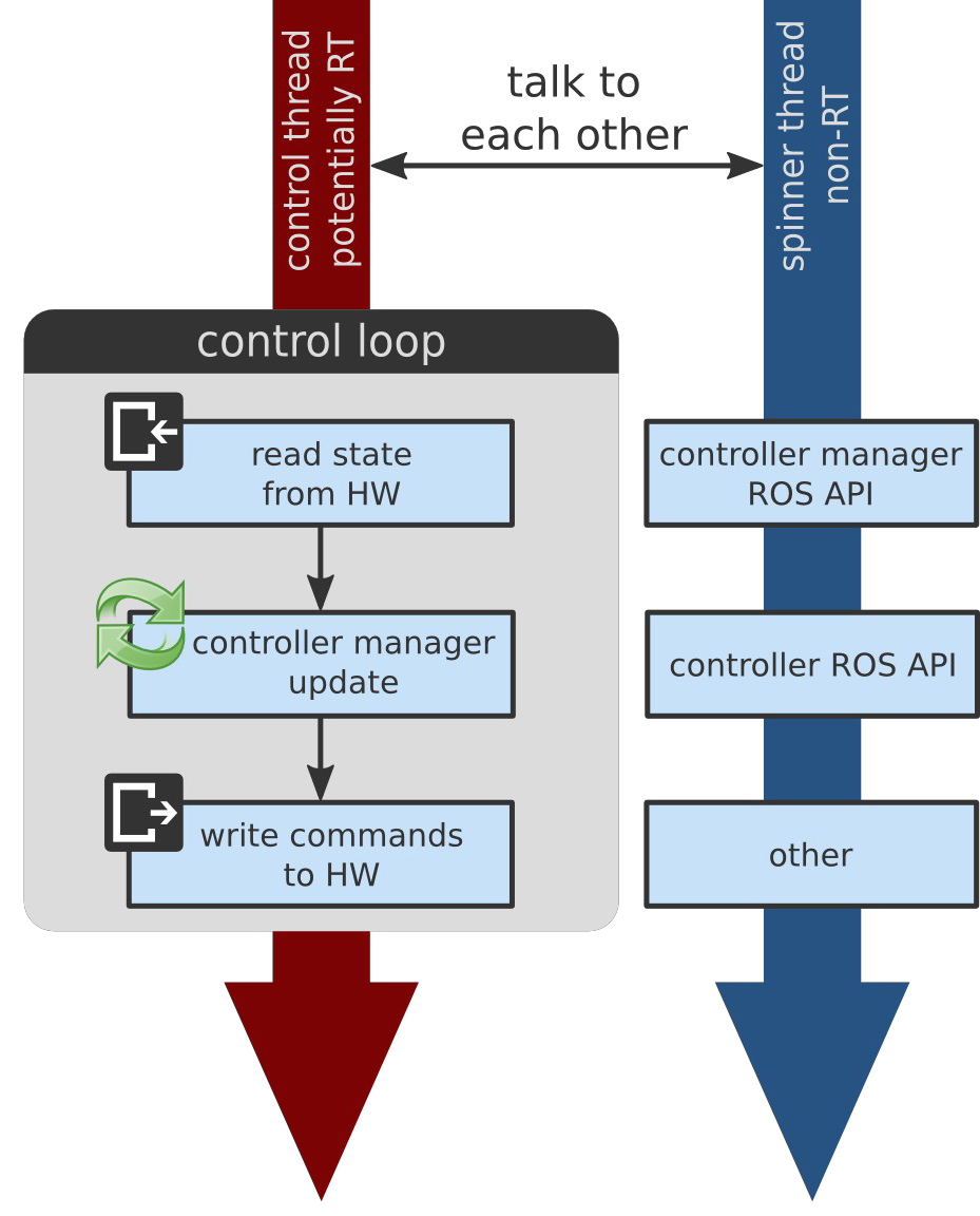
As we see in the image above, the spinner thread
There are different kinds of callbacks that are serviced by this thread. First, those from the controller manager API and second, there’s the ROS API from your controllers which is custom and up to you. And finally there might be other callbacks registered which depends on your setup.
It is important to mention, that we have the computations, which are non real-time in a separate thread. Having these non real-time computations separate means that we respect requirements from real-time applications but also deterministic execution.
In the code example above we don’t have real-time constraints because it’s a slow robot operating at 10 Hz. However, it also makes sense in this example to have the threads separate. For example, imagine a robot with 10,000 joints that has a controller which needs to parse its URDF while loading. In this example, there is no way to guarantee that parsing that URDF will take less than 0.1 seconds.
If we would serialize everything in the same thread then such long lasting operations would not guarantee to respect the rate of the control loop. Therefore, these operations are separated into a spinner thread (even if we’re not using a real-time operating system).
Because we have two threads, they need to talk to each other, as we can see in the image above. We have to handle concurrency with care, especially with respect to the control thread. Because it operates in real-time we have to make sure that we never block it to avoid suffering from priority inversions or other bad things that might happen.
To deal with concurrency and other things there’s a package that’s called realtime_tools which has tools that are usable from a hard real-time thread. It includes:
- RealtimePublisher: publish to a ROS topic
- RealtimeBuffer: share resource with non real-time thread.
- RealtimeClock: query estimates of the system clock.
- …
The Control Loop Extended
Let’s now look at the complete control loop used in ROS control’s framework:
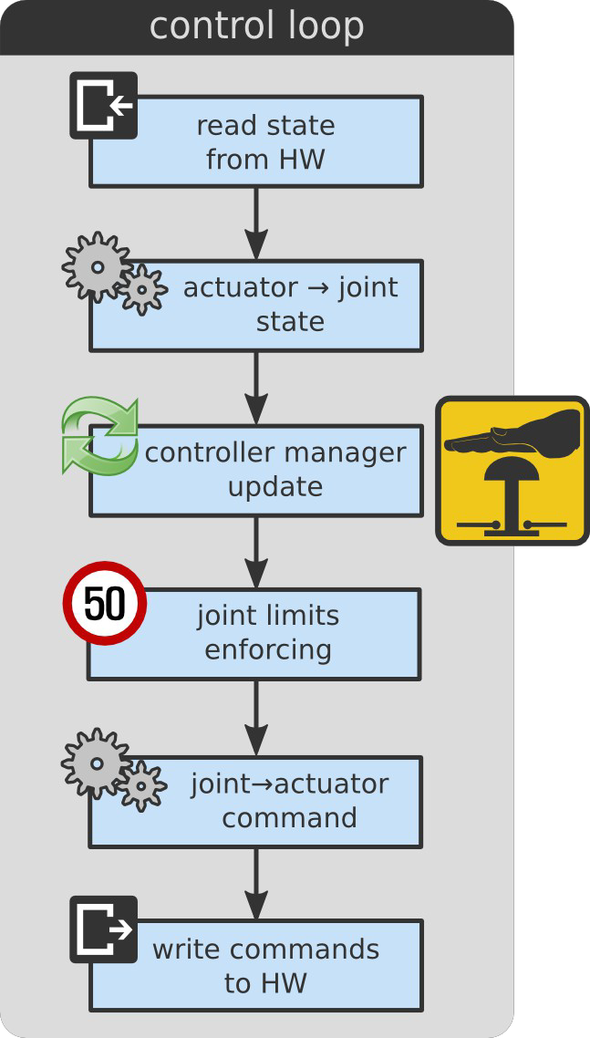
With this extended control loop we can make use of mechanical transmissions, take care of joint limits and provide emergency stops.
Mechanical Transmissions
If your hardware doesn’t take care of mechanical transmissions by itself than we have to do this in software.
For this, there is a package called transmission_interface which contains data structures for representing mechanical transmissions, and methods for propagating position, velocity and effort variables between actuator and joint spaces.
In the same spirit as the hardware_interface package, this package wraps existing raw data (eg. current actuator position, reference joint command, etc.) under a consistent interface. By not imposing a specific layout on the raw data, it becomes easier to support arbitrary hardware drivers to software control.
The transmission_interface is not used by controllers themselves (it does not implement a HardwareInterface) but instead operates before or after the controllers update, in the read() and write() methods (or equivalents) of the robot abstraction.
The following transmissions already exist and are ready to use:
- Simple reducer
- Four-bar linkage
- Differential
There are plugins that help you in loading transmissions from the URDF and thereby simplifies the process of populating the hardware_interface::RobotHW interfaces.
Without these plugins it would be very complex to populate your robot hardware interface.
The following URDF xml snippet shows a configuration for a simple reducer. This is what you have to put in your URDF.
<transmission name="arm_1_trans">
  <type>transmission_interface/SimpleTransmission</type>
  <actuator name="arm_1_motor">
    <mechanicalReduction>42</mechanicalReduction>
  </actuator>
  <joint name="arm_1_joint">
    <hardwareInterface>hardware_interface/PositionJointInterface</hardwareInterface>
  </joint>
</transmission>
Here you’re specifying the type of the transmission the name of the actuator and joint that you were relating to one another and things like the mechanical reduction and the type of hardware interfaces that you’d expect to expose.
Safety Issues
You might be interested in enforcing joint limits before you send the commands to the robot hardware.
For this, there is a package called joint_limits_interface. It is the last line of defense before commanding hardware
- don’t trust controllers. It is implemented using simple and fast low-level stragegies.
Inside the package you find
- data structures for representing joint limits.
- Convenience methods for populating these data structrues from:
- URDF
- yaml (similar to MoveIt! + jerk)
- Methods for enforcing joint limits
- soft-limits (PR2 like) and clamping strategies
- work for different hardware interfaces
The following example curves, generated from real data, explains the joint limits implementation:
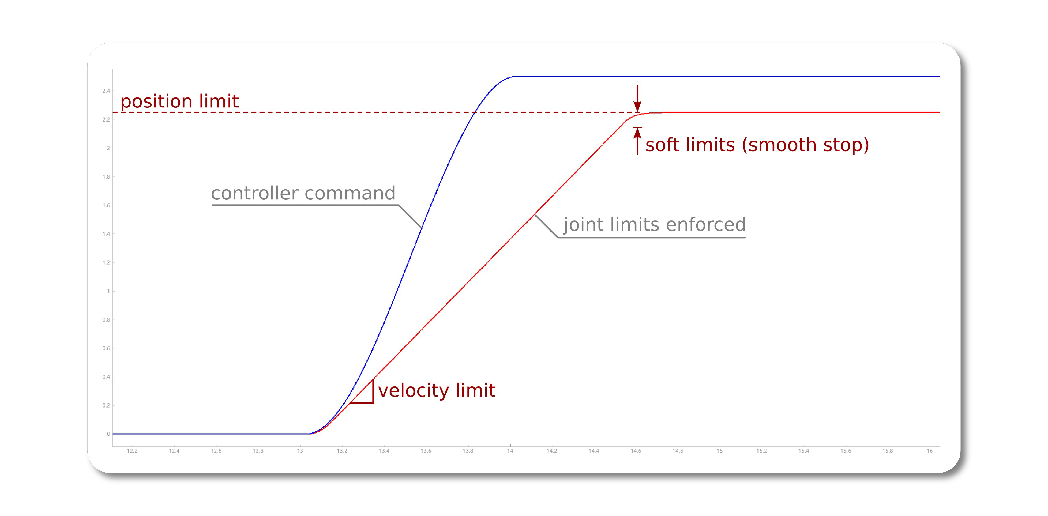
The blue curve shows the command of a controller that we don’t trust. The red line shows the result after enforcing the joint limits. At the bottom we see, that the velocity limit is enforced and at the top the position is enforced too. However, it is a smooth stop and we see that it is not a hard clamping at the top, because we used a soft limit specification.
The last issue that is also concerned with safety is the emergency stop (E-stop). The E-stop is typically robot specific which means you have to take care of its implementation. There’s also the distinction between an emergency stop, which is usually much harder where you for example remove energy sources, and there’s also the notion of a protective stop which is meant to reduce risks and control hazards.
Relevant standards:
- ISO 10218-1:2011 Robots and robotic devices - Safety requirements for industrial robots
- ISO 13482:2014 Robots and robotic devices - Safety requirements for personal care robots
The issue that remains, whatever you do in case of an emergency stop, is that you have to recover from it. The question that remins is: What is the sane thing to do when you release the stop? There are potentially many controllers running that do different things. This means that there is no one size fits all solution on what you should do.
One interesting solution to this is that you should let controllers decide what to do in case of an emergency stop. The controller manager has this feature that it can be updated with an optional prior that says controllers reset. This means that in a single control cycle you stop all running controllers, followed by starting them and finally you update them. If we adhere to the typical policy that, explained before, is to stop and thereby cancel all goals and then start, which enters semantic zero mode, that when you update, you have the same behavior.
This concludes the part of the control loop.
Reference
- ROSCon 2014 talk and the presented slides


Comments