Introduction
This blog post describes how to connect the Pololu MinIMU-9 v5 to a Rasperry Pi 3 B+ and use the RTIMULib2 to visualize the inertial measurement unit (imu) data such as orientation and acceleration.
Prerequisites
This post requires that you have setup a Rasperry Pi running Linux Mate described in another blog post or the standard Raspbian OS and the Pololu MinIMU-9 v5 from Pololu.
Hardware
The MinIMU-9 v5 PCB houses two chips. One is the LSM6DS33 which contains a gyroscope and a linear accelerometer and the other one is the LIS3MDL that contains a 3-axis magnetometer. Pololu also supplies a great free piece of software (minimu9-ahrs) for Raspberry Pi for reading sensor data from Pololu IMU boards over I²C. When I first got the board, I tested it with this software and it worked great. However, because I require ros support I decided to use the RTIMULib2 which I will explain in more detail later.
Hardware Connection
The MinIMU has six pins, which are shown in the following figure. Beside the VDD and GND to power the imu, the SDA (data signal) and SCL (clock signal) pins are important.
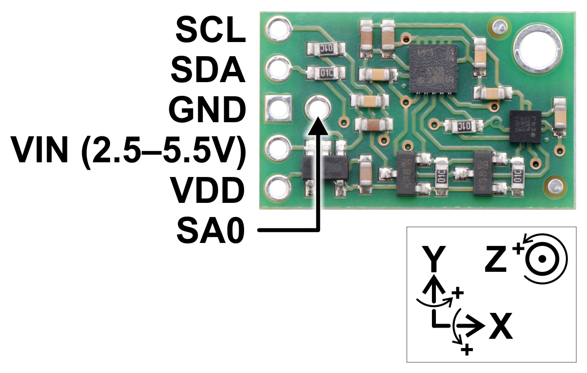
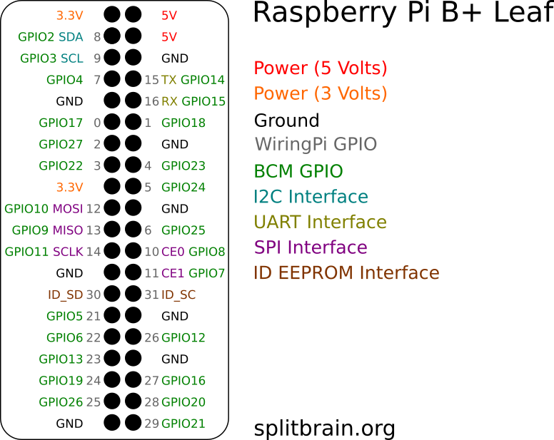
To communicate with the IMU the GPIO pins of the raspberrypi can be used. By taking a look at the Raspberry Pi bus leaf from splitbrain.org, we see that GPIO 2 and 3 are called SDA and SCL, which can be direclty connected to the corresponding imu pins.
For test purposes I used a bread board and four male to femal jumper wires to to connect the PCB to the GPIO pins.
RTIMULib2
The RTIMULib2 did not support the LSM6DS33 and the LIS3MDL which are on the MinIMU-9 v5 PCB. Therefore, I wrote a driver to support the imu which can be found in this github repository.
To install the library, just clone the repository
git clone https://github.com/fjp/RTIMULib2Then cd into the new RTIMULib2 folder and build and install the library
cd RTIMULib2/RTIMULib
mkdir build
cd build
cmake ..
make
sudo make install
The last command copies the library into the shared library path LD_LIBRARY_PATH of linux.
To run a test program, change into the Linux folder and build the example programs in there.
cd RTIMULib2/Linux
mkdir build
cd build
cmake ..
make
These commands will create new folders inside the build directory which contain the program executables.
The visual demo can be executed with the following lines of bash code:
cd RTIMULib2/Linux/build/RTIMULibDemoGL
make
./RTIMULibDemoGL
This should establish a connection to the connected IMU and open a Qt GUI that lets you see the orientation of the imu.
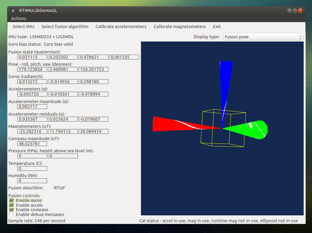
The first time you start the GUI a file called RTIMULib.ini is created which is used to store the imu settings (address of the chips, fusion state) and calibration data. Furthermore, the IMU is not calibrated and will result in poor tracking behavior while rotating. Therefore the sensors (magnetometer, accelerometer and gyroscope) need to be calibrated which I will explain in the next section.
Calibration
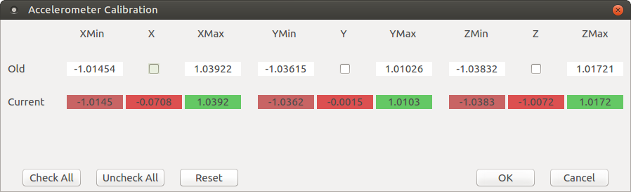
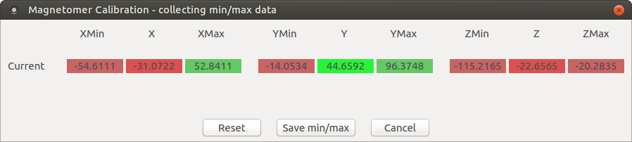
Calibrate the magnetometer and the accelerometer using the buttons on top of the gui. A tutorial on how to calibrate these sensors is given in the Calibration.pdf in the repository.
Here are two screenshots of the values after I calibrated the two sensors:
Troubleshooting
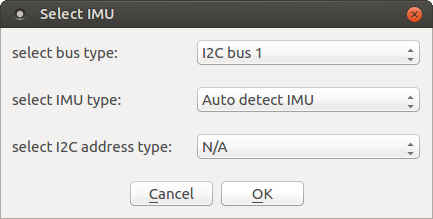
If you have troubles to connect the IMU, take a look for errors at your terminal output and try re-connect the IMU and use the correct settings. Using the auto detect should help to find any supported imu.
Future Work
Instead of using the RTIMULib2 it should be possible to use the output from the mentioned minimu9-ahrs program and create a ros node with this code.


Comments