Assembly of the robot platform and the components.
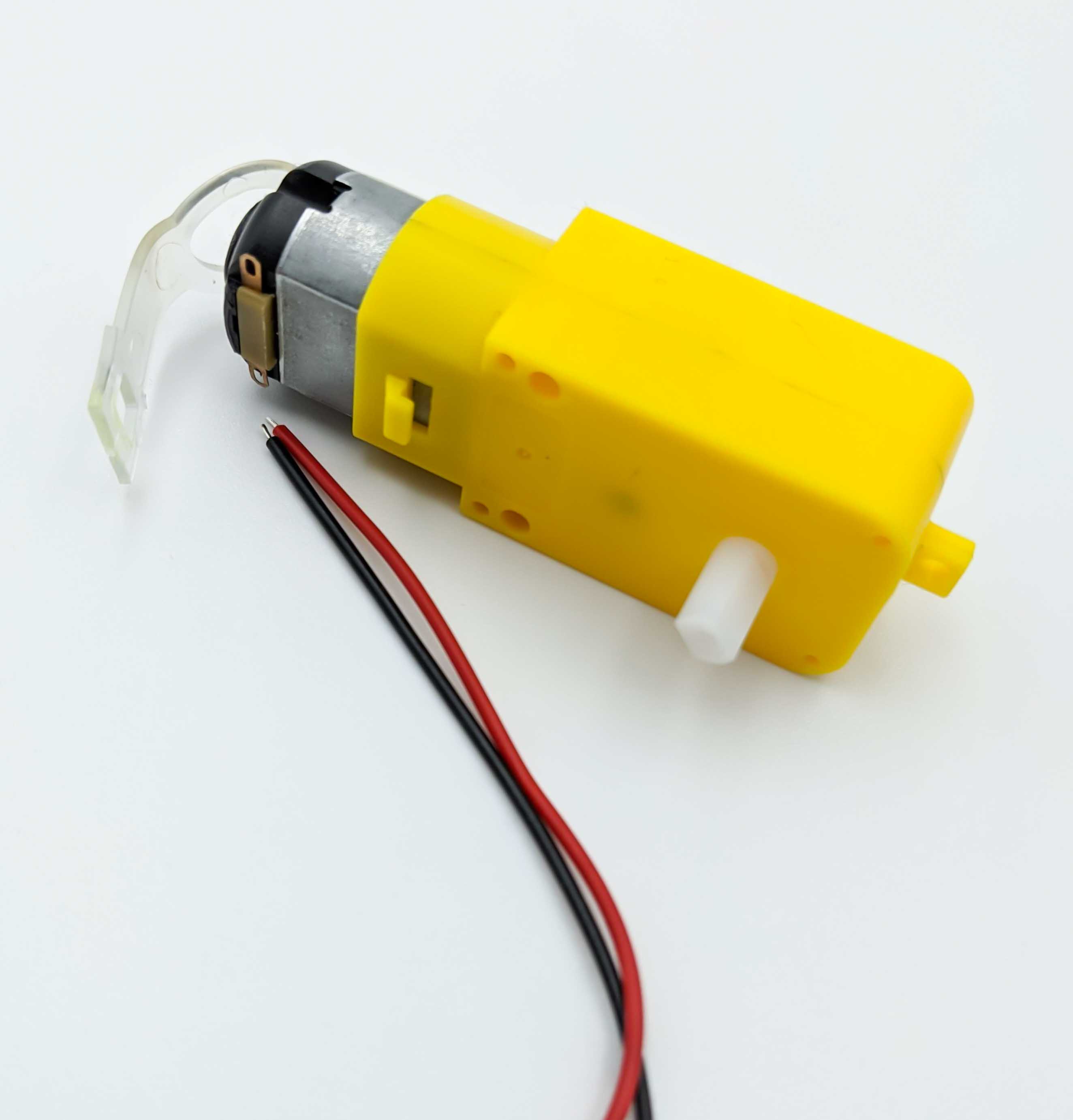
Motors
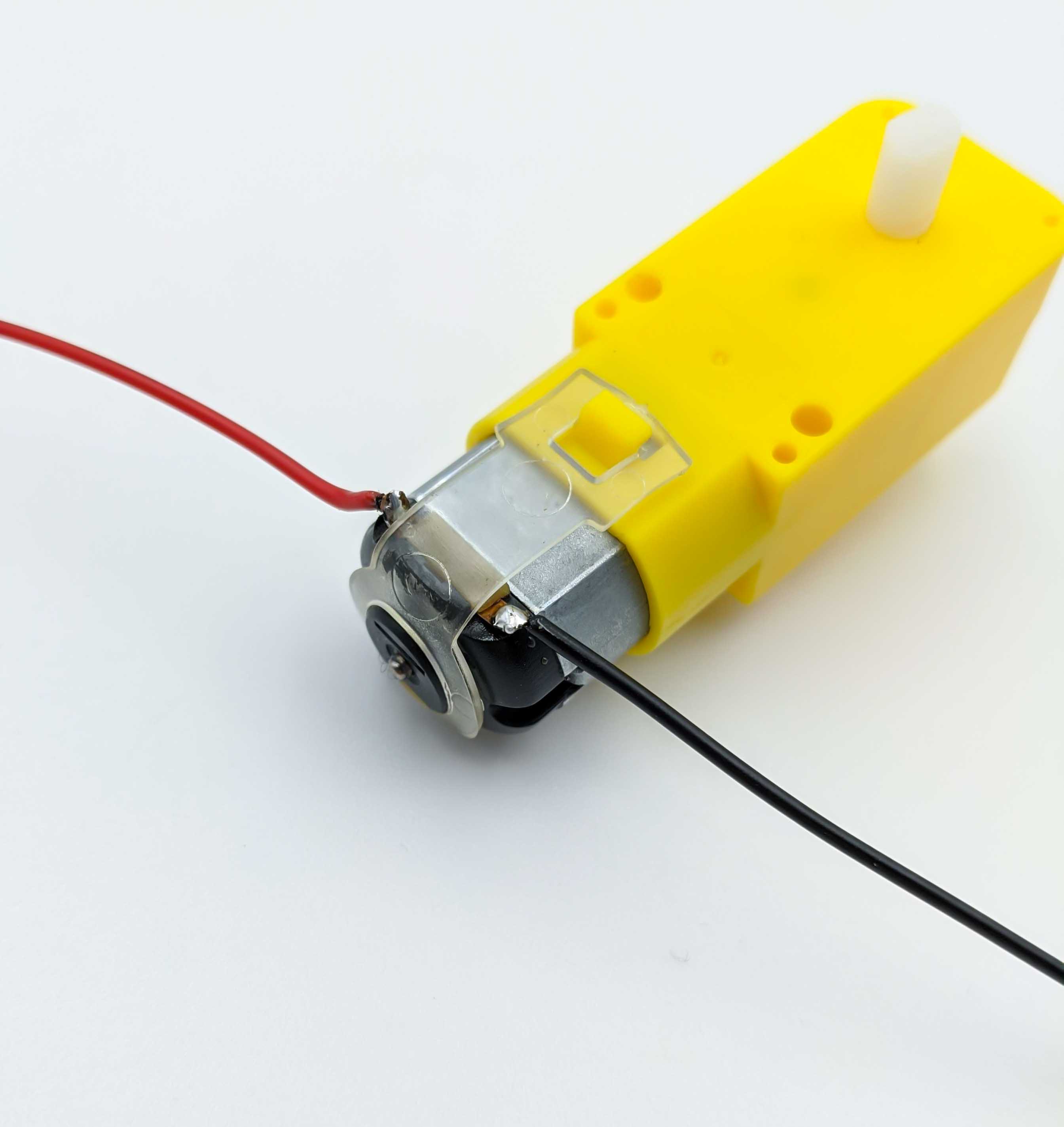
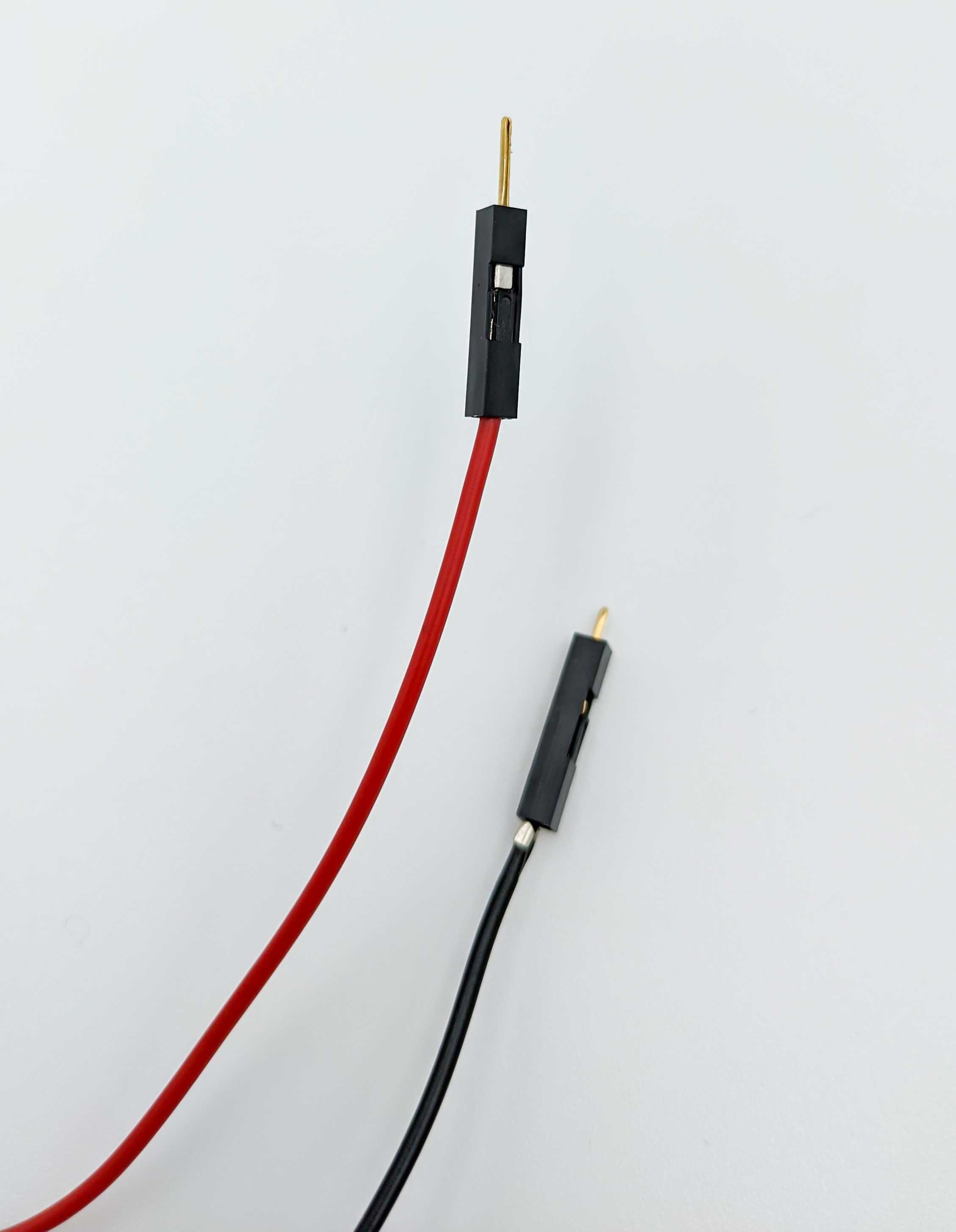
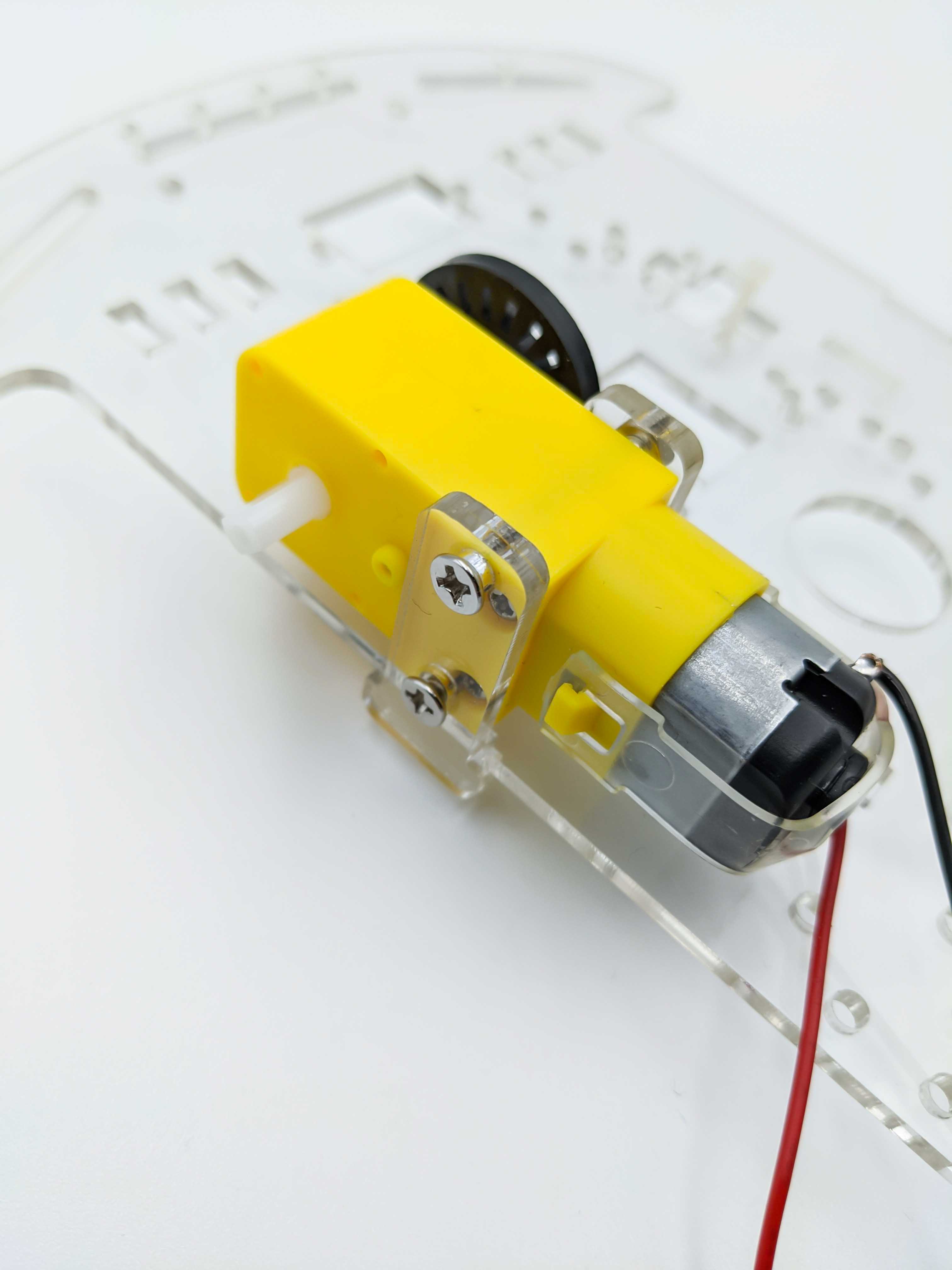
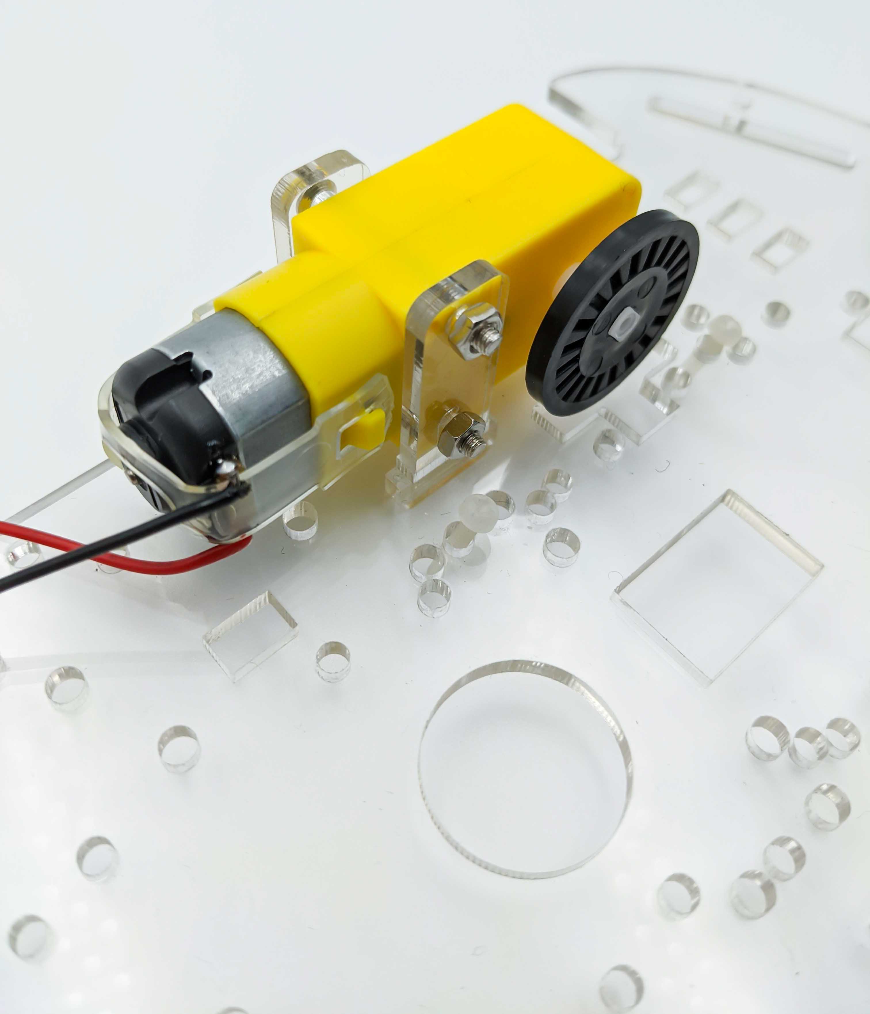
First we solder the plus and minus wires to the brushed motor. The polarity isn’t really important because it can be changed later in software or by changing the polarity in the motor driver.
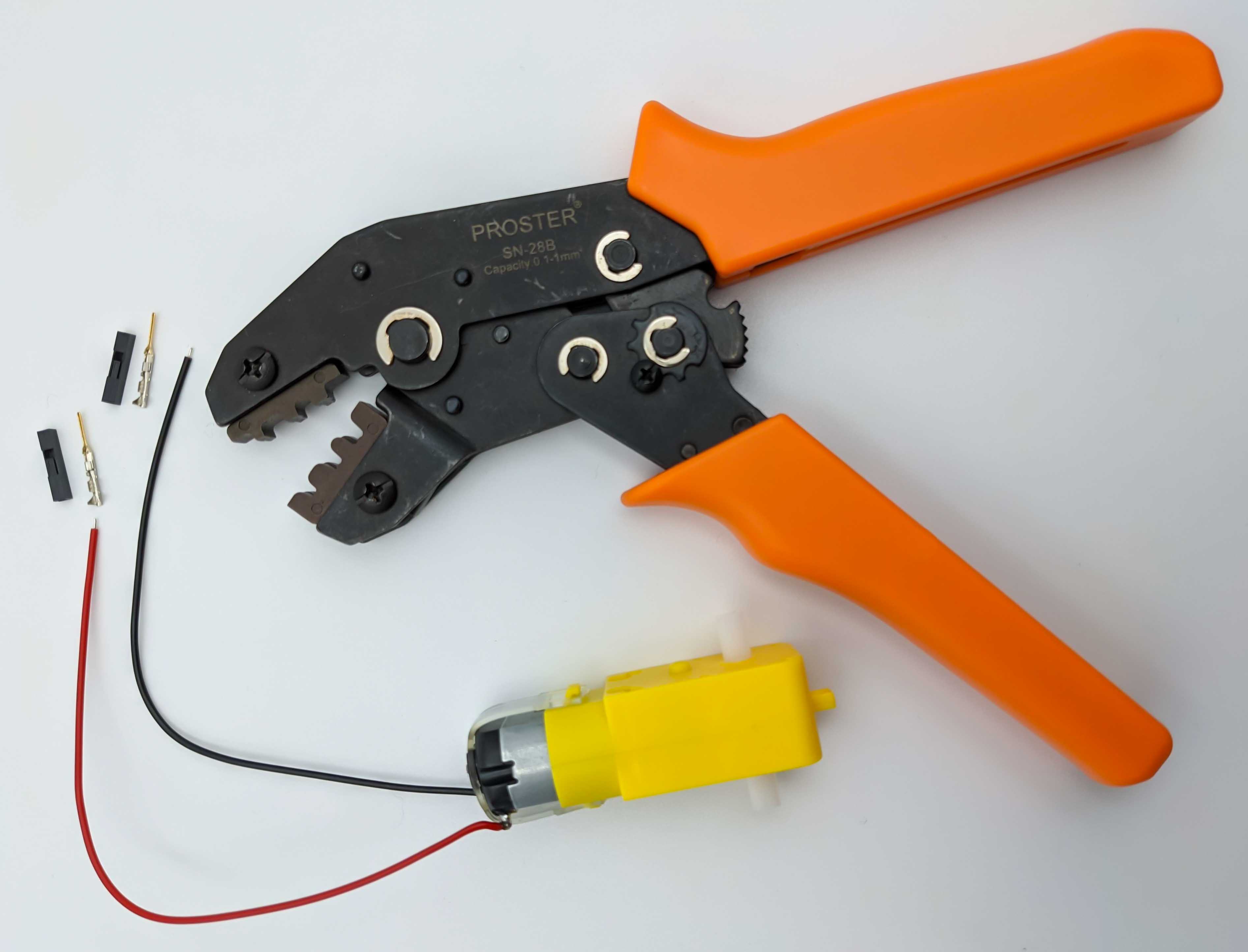
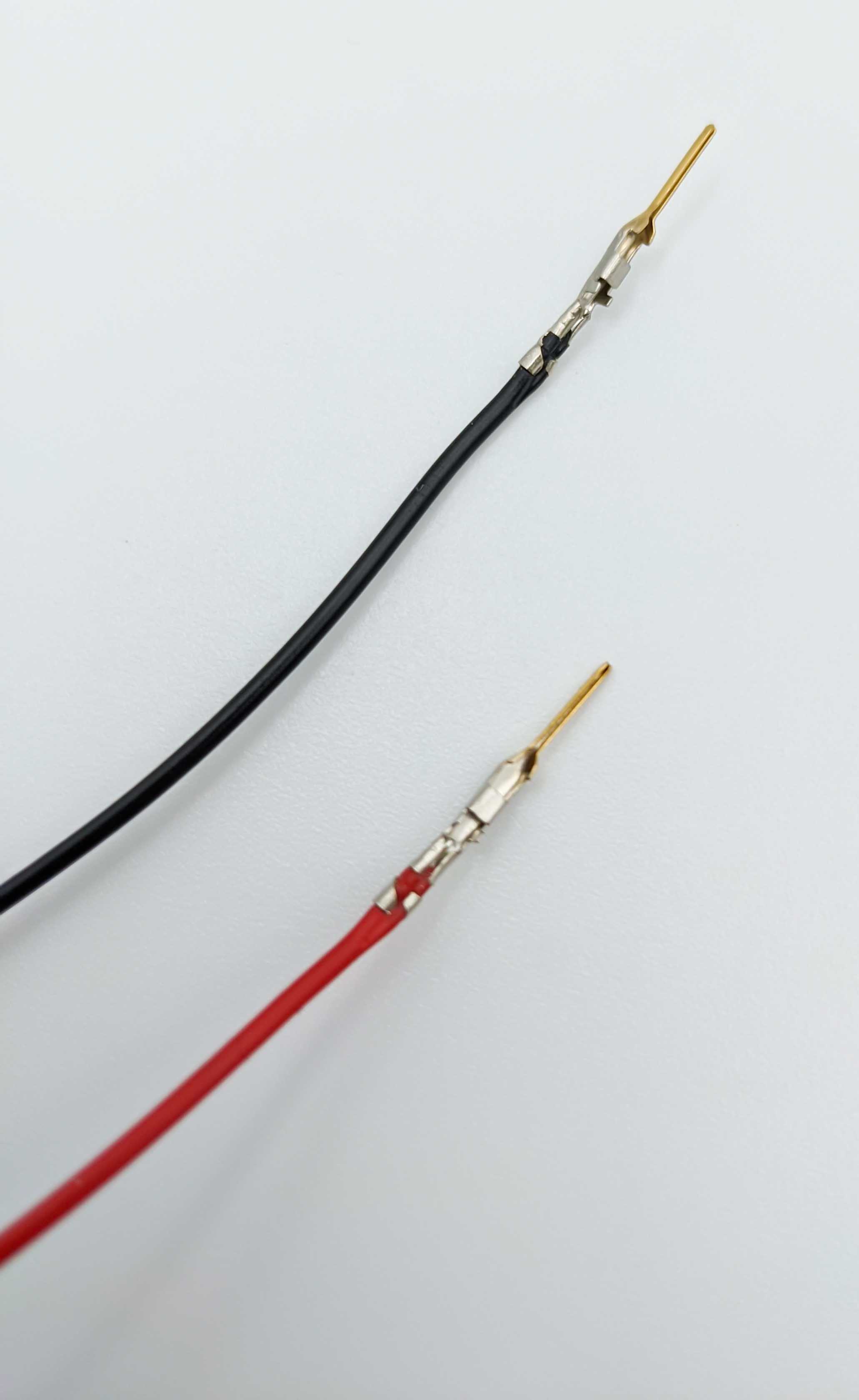
For the other ends of the motor wires we can use Dupont connectors or solder them directly to the motor driver.
Motor Driver Preperation
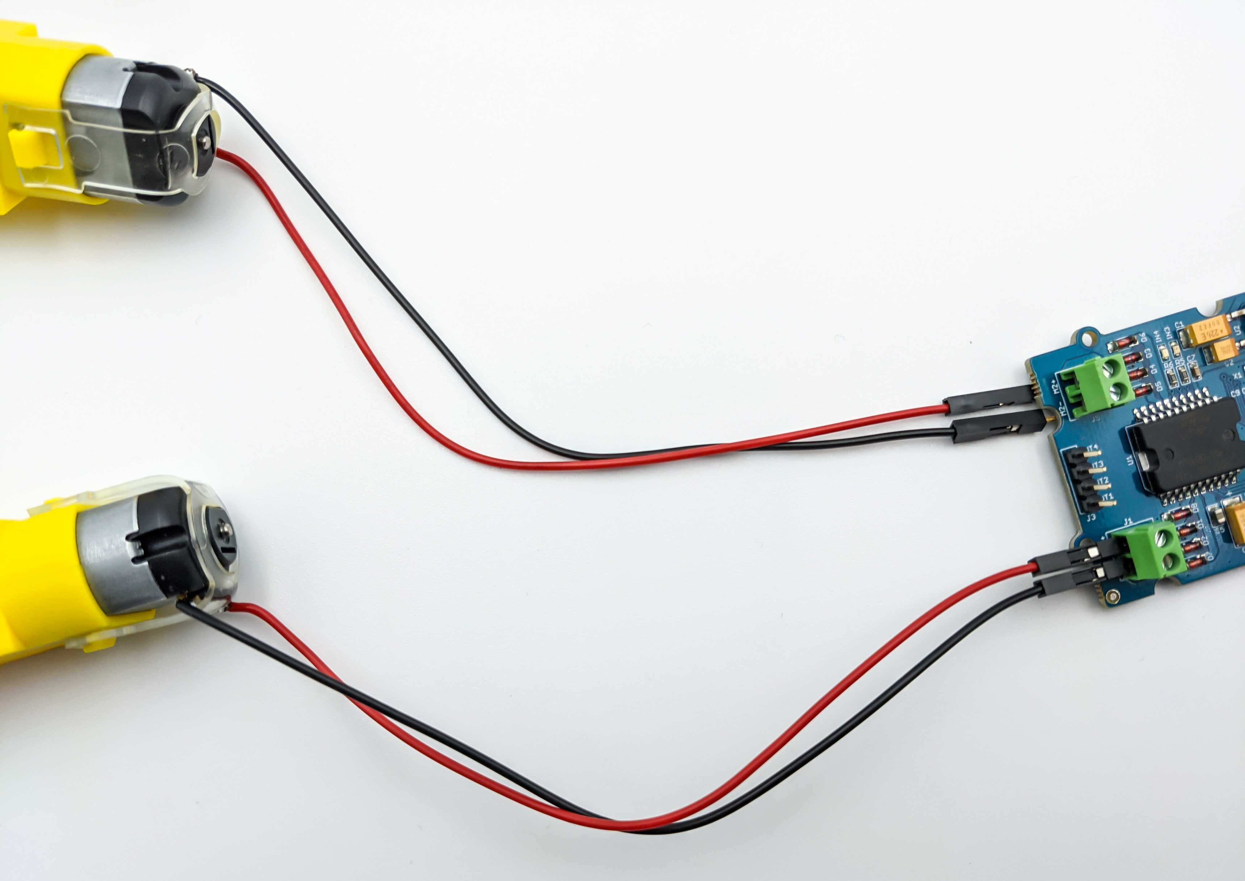
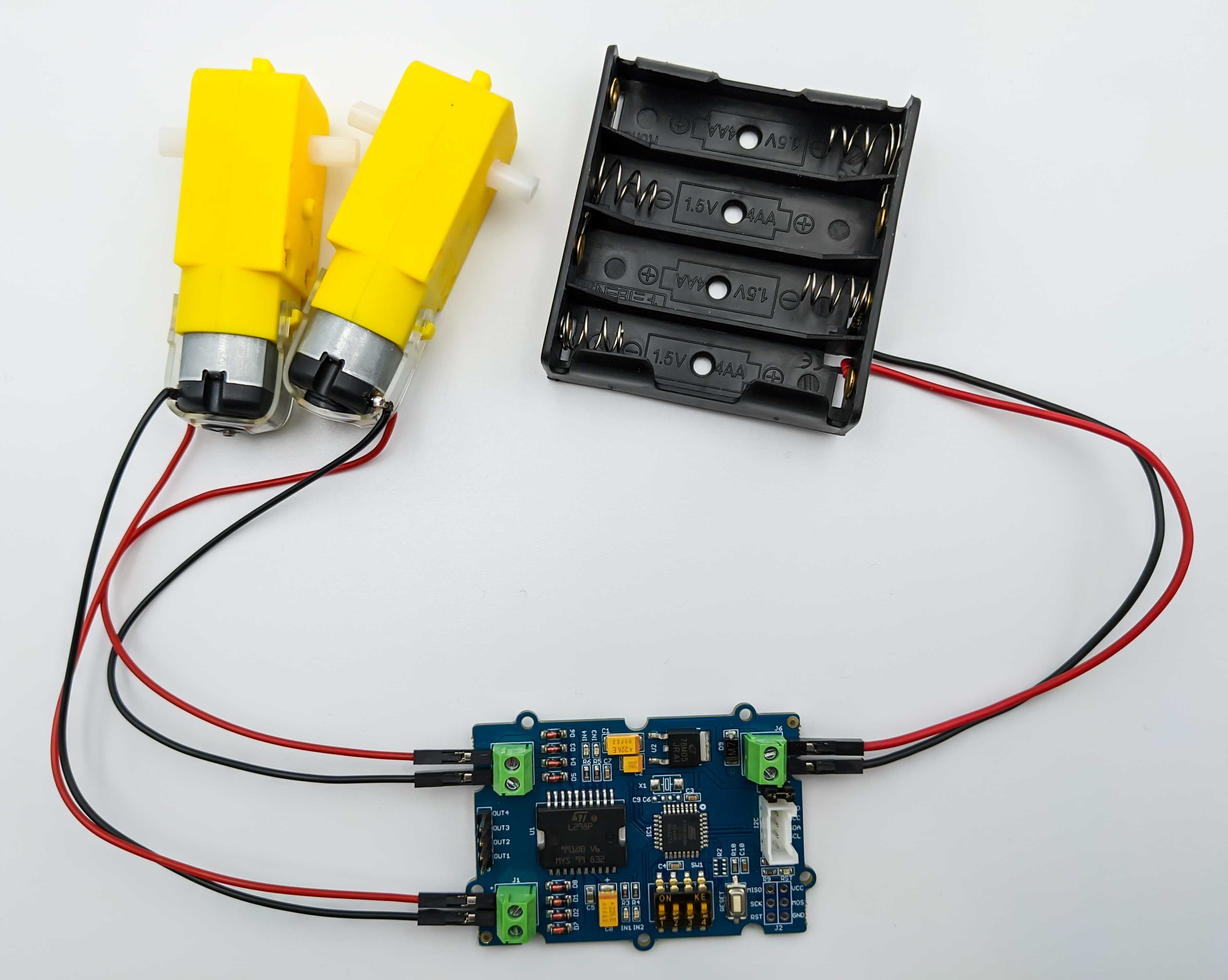
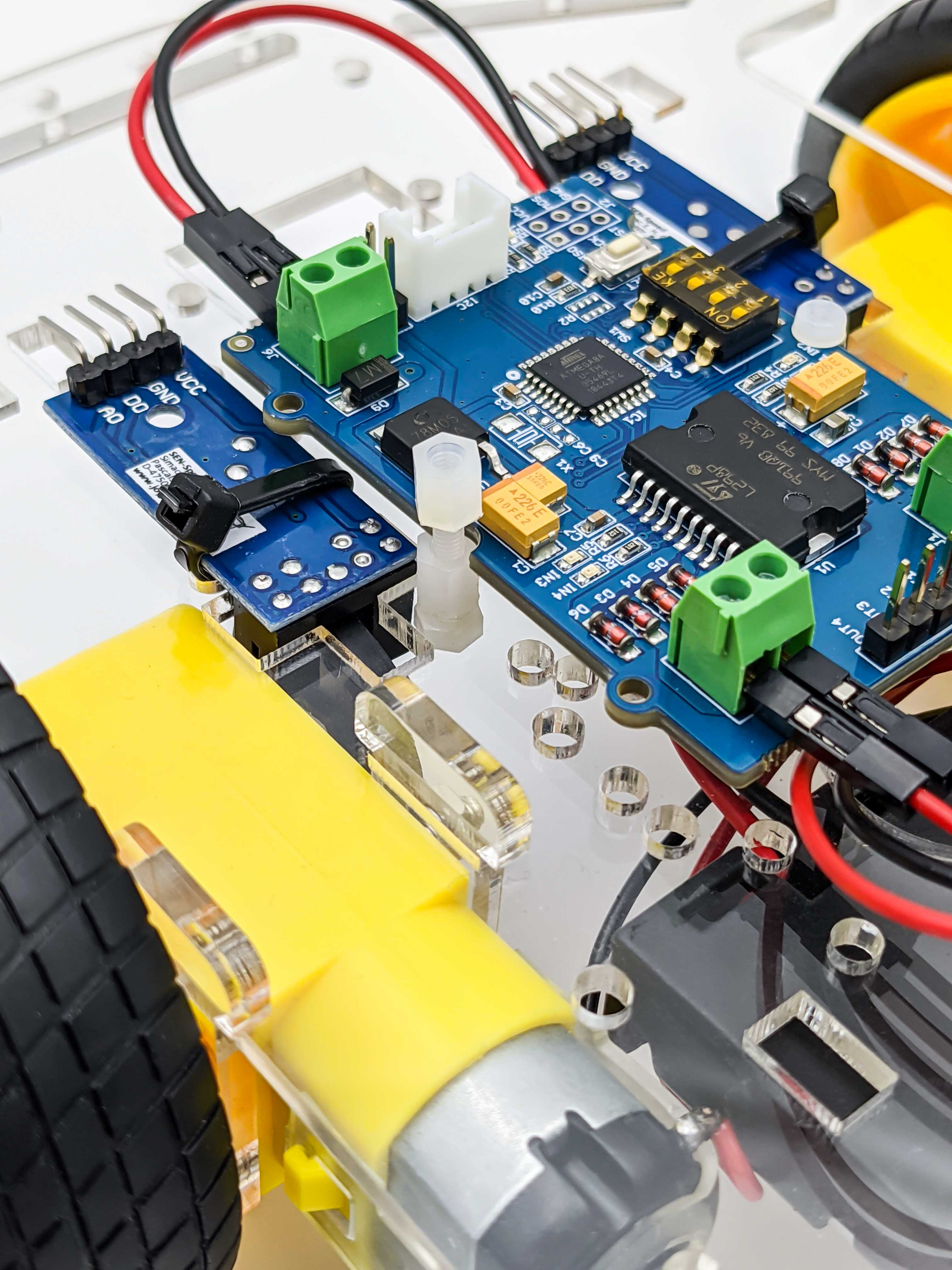
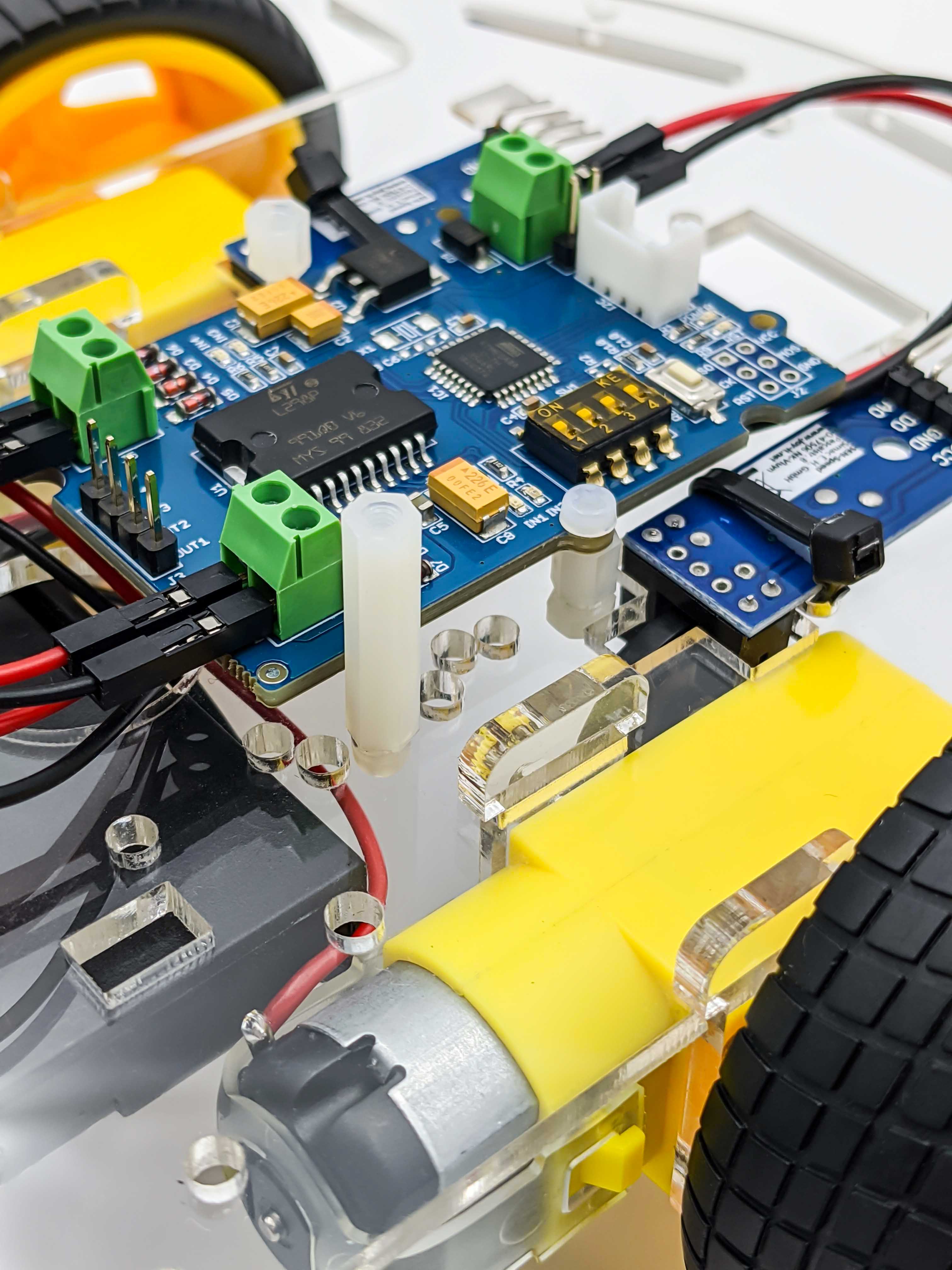
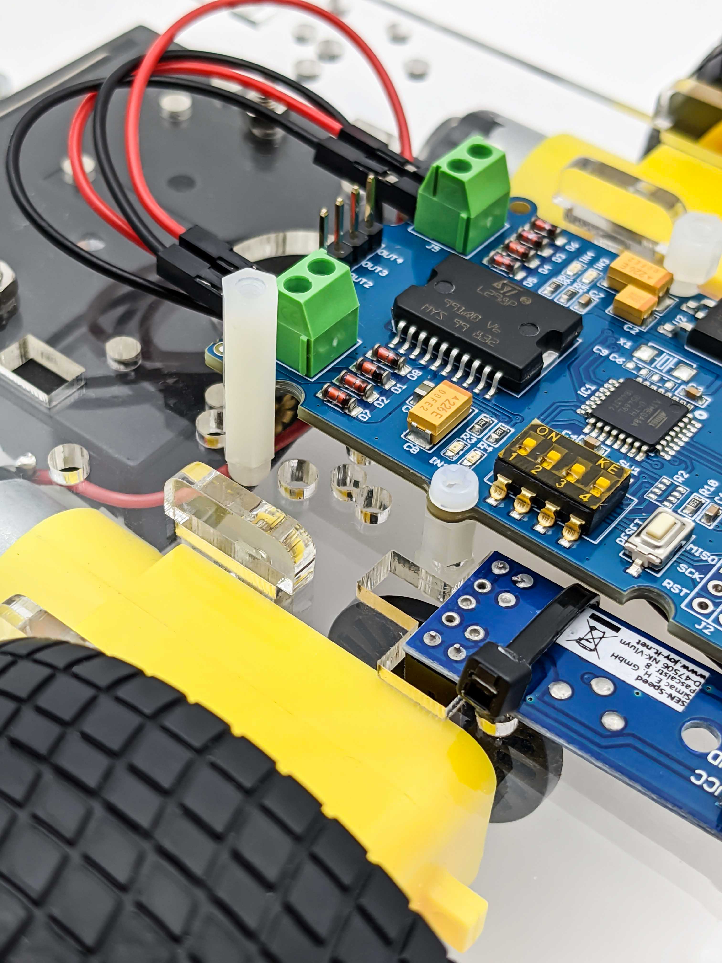
After preparing the motors we can connect them to the to screw terminals labeled M1 and M2 on the motor driver. The motor driver will get its power from the battery holder case supplied with the robot car kit.
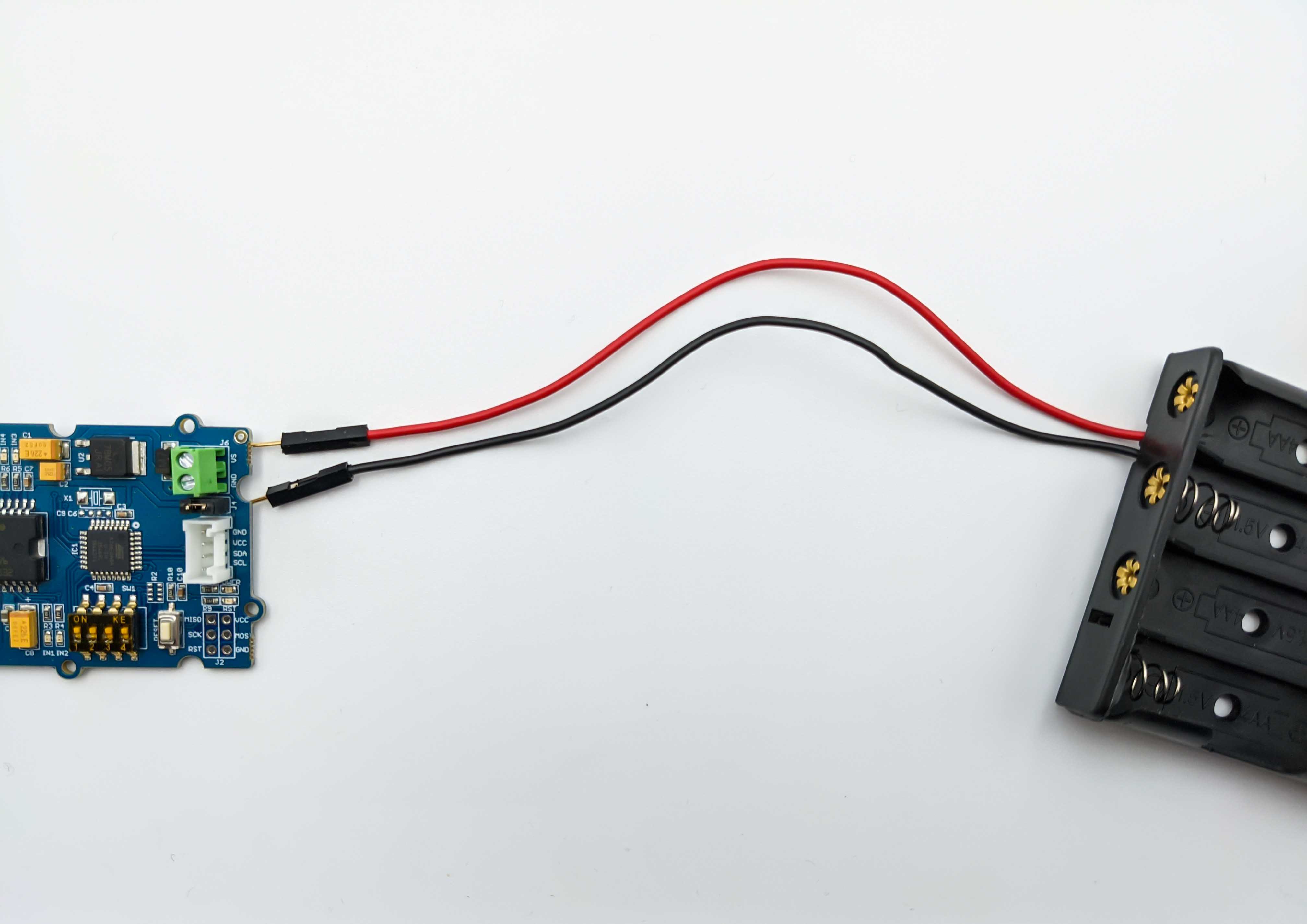
The input voltage on the screw terminals is regulated to 5V and connected to I2C +5V via a jumper (J4). Make sure to remove jumper because we don’t want to provide 5V power on the I2C +5V wire. The jumper is only useful if 5V should be supplied to the I2C bus, which is not required because the Raspberry Pi will be powerd with an additional powerbank.
Robot Base
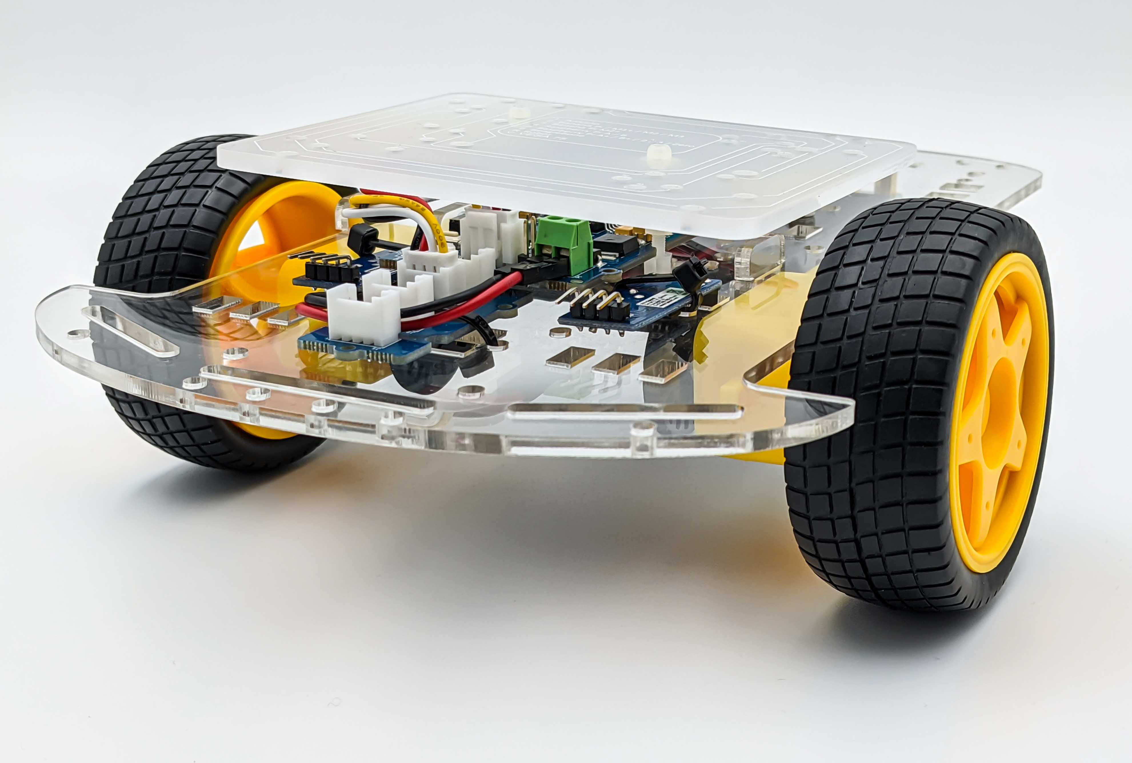
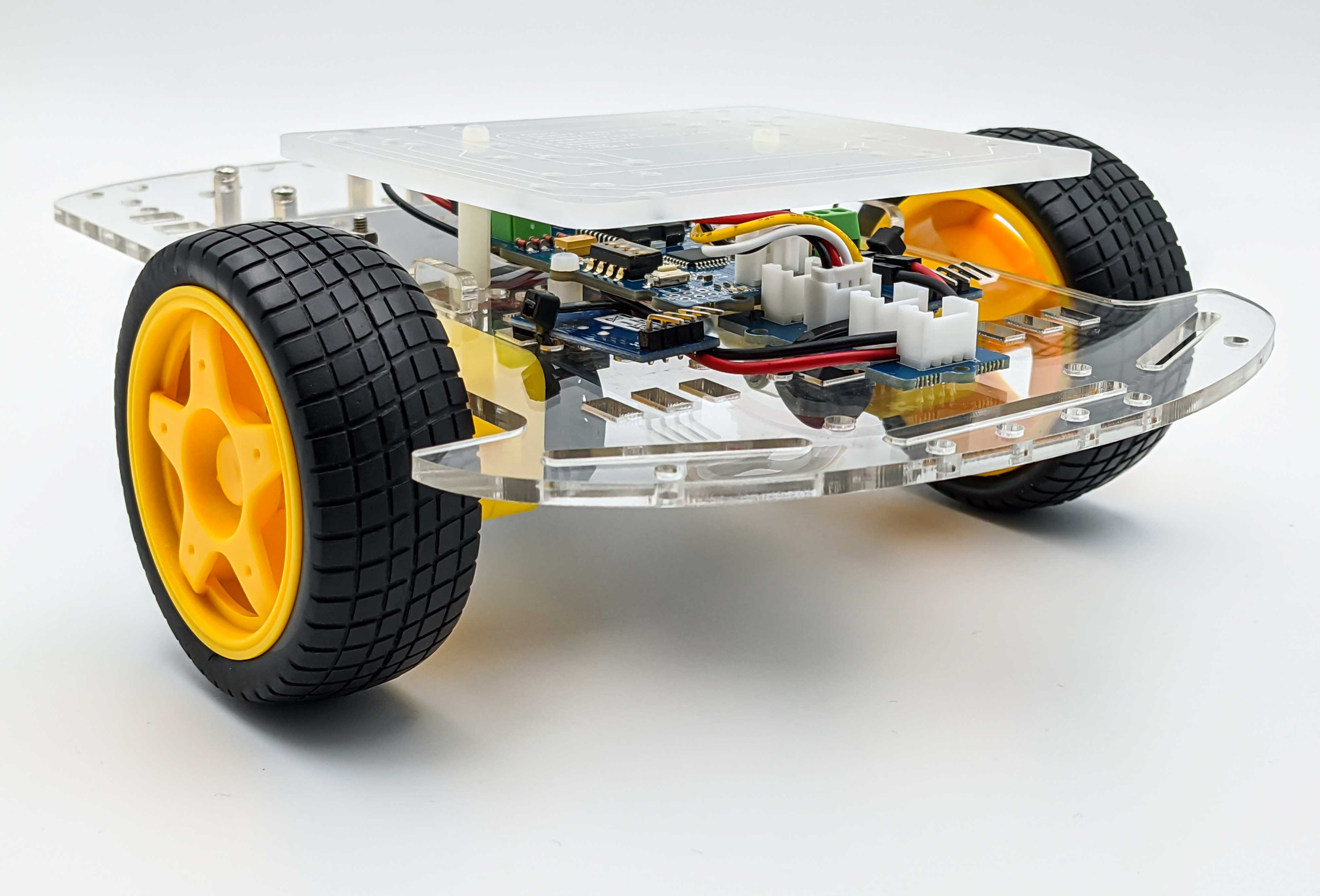
The acrylic chassis has many holes which allow to mount a mounting plate that can hold different development boards. It allows also to mount a Raspberry Pi 4 B, which will be used in this project. An instructions manual (seems to be only available in german) can be helpful but only to a certain degree because we will use different components that requires placing screws into pre drilled holes where they are suited.

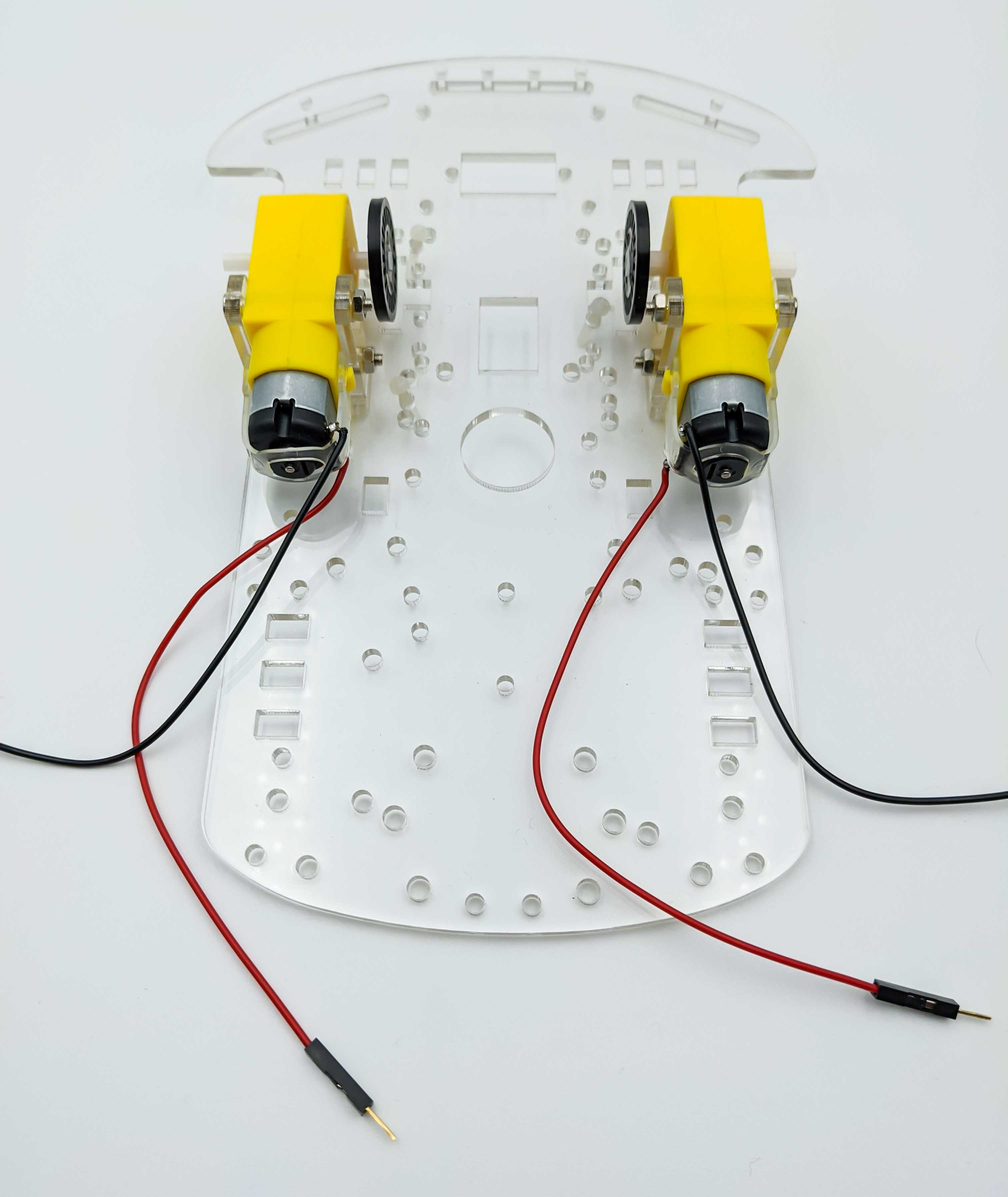
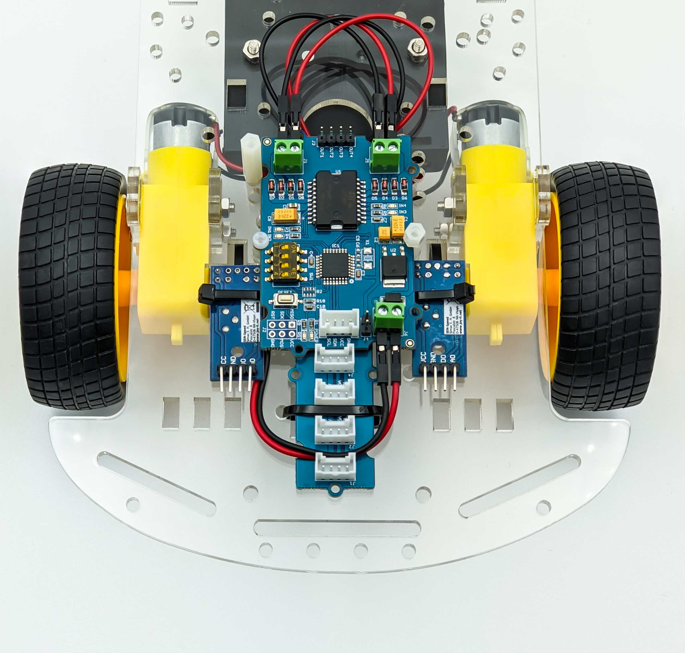
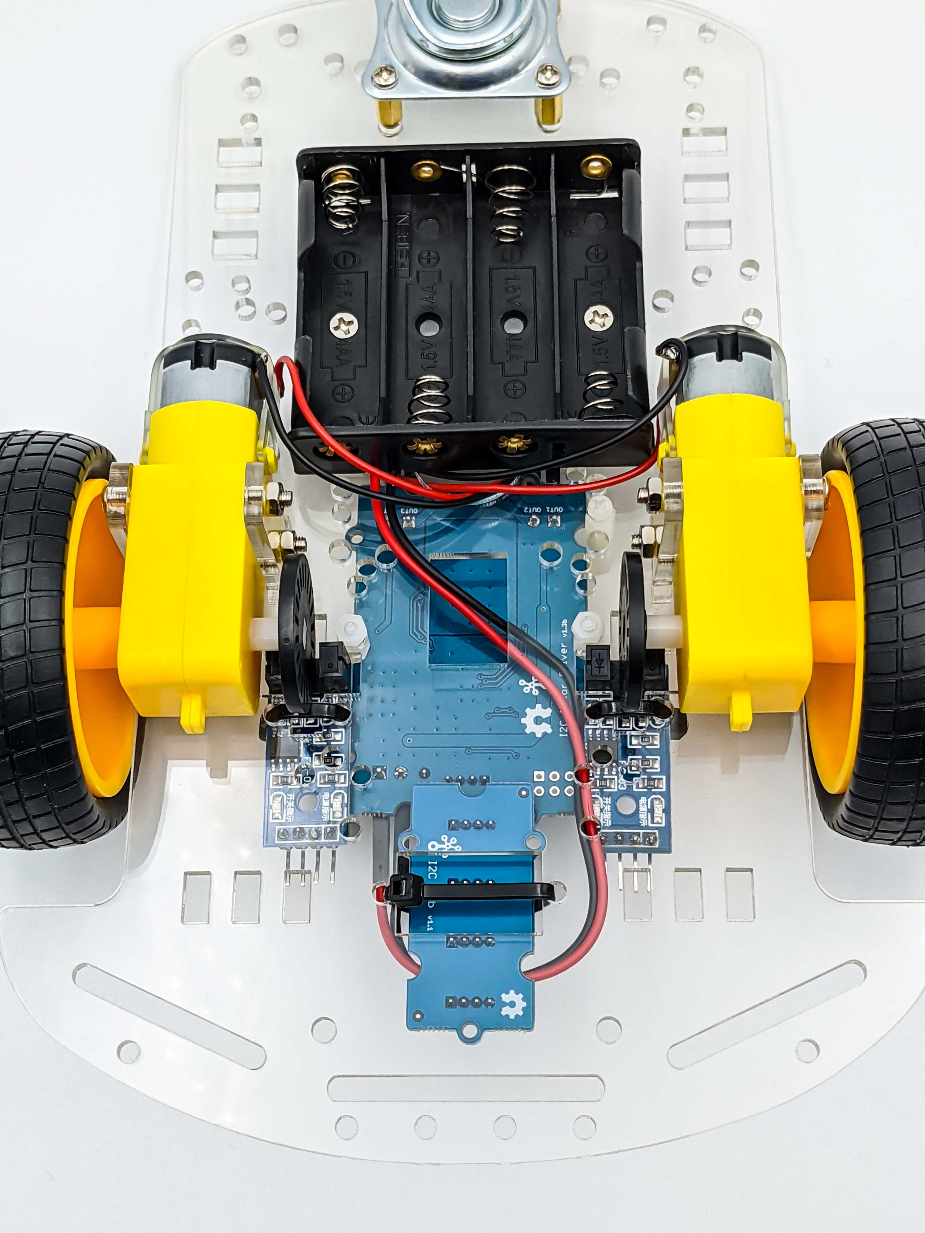
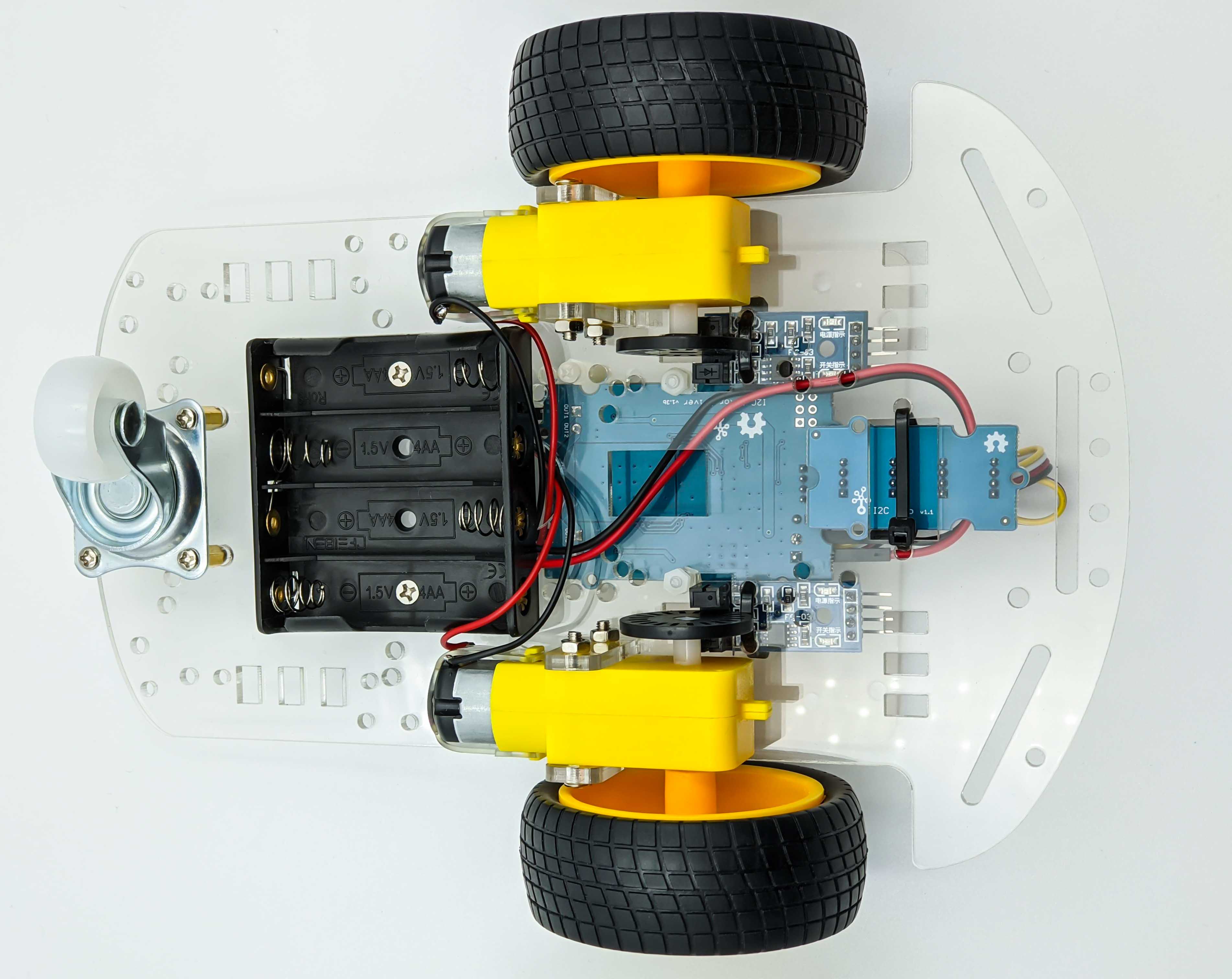
The following images shows how I assembled the robot car kit. It is important to mount the motors on the correct side of the acrylic plate becasue otherwise the mounting plate where the Raspberry Pi will be attached to will not fit to the pre drilled holes.
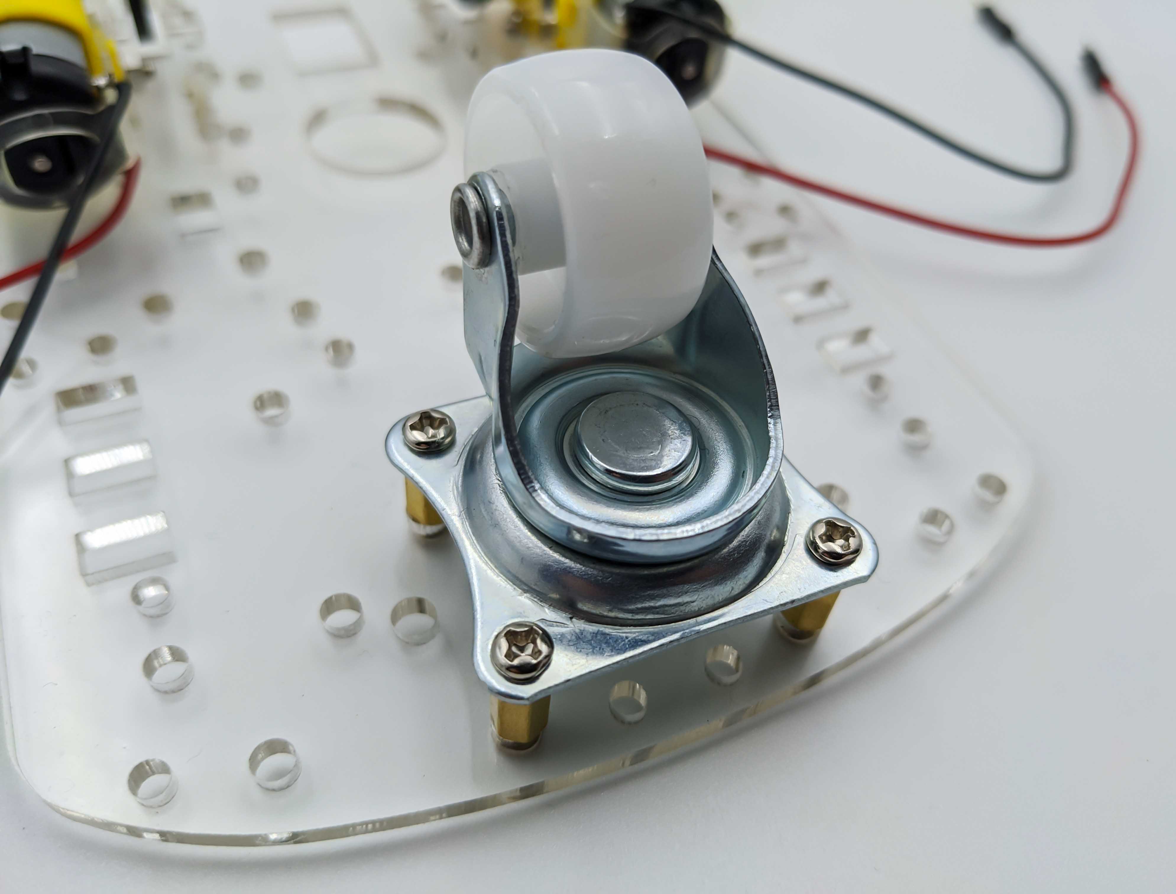
Castor Wheel
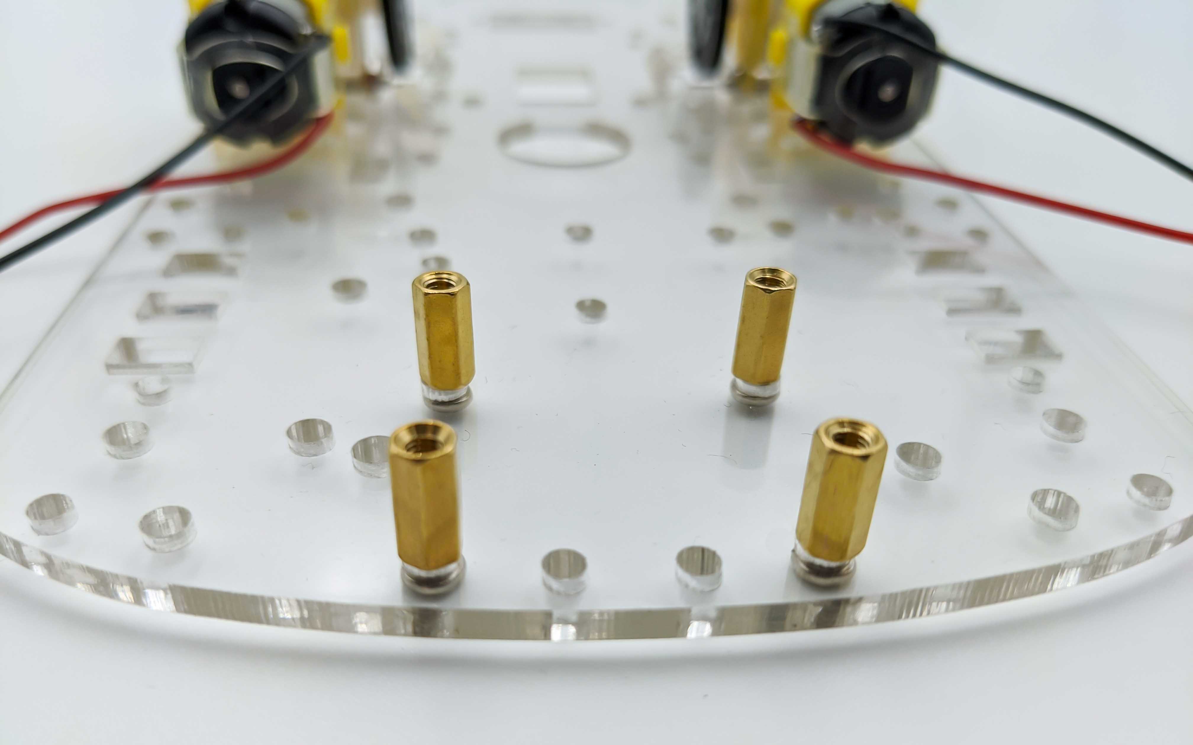
The castor wheel is brought in position by four distance bolts and mounted with eight screws.
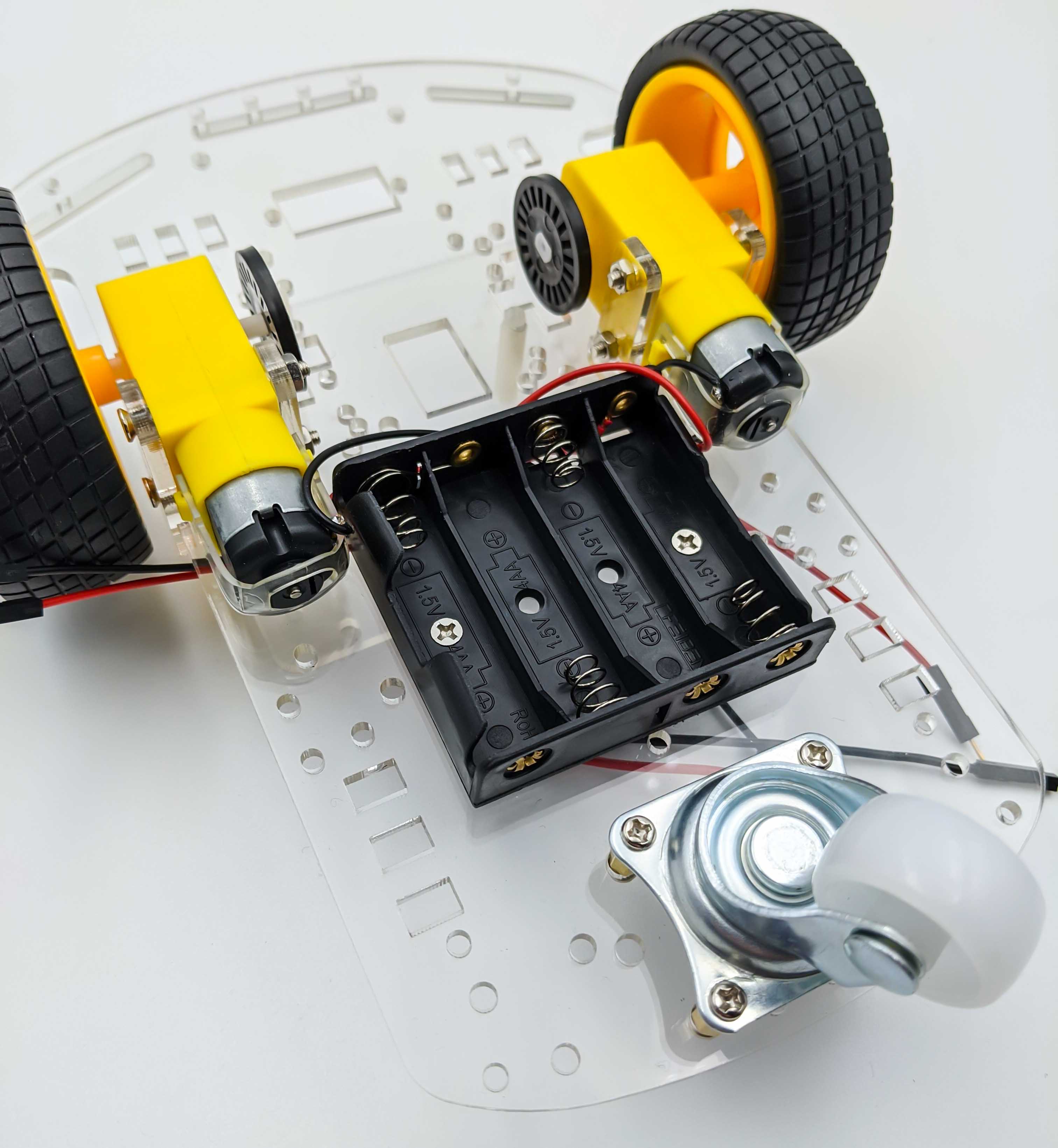
Battery Holder Case
To power the motors the provided battery holder case will be used, which holds four AA batteries $4 \cdot 1.5\text{V} = 6\text{V}$ to power the two gearbox motors via the motor driver.
Therefore we add the battery holder case that I placed on the bottom of the acrylic chassis instead of on top of it as suggested in the instructions manual. The reason is that we will use an additional USB-C powerbank to power the Raspberry Pi 4 B.

Powerbank for RPi
As mentioned the robot will be equipped with a USB-C powerbank to supply the RPi 4 B with 5 V.
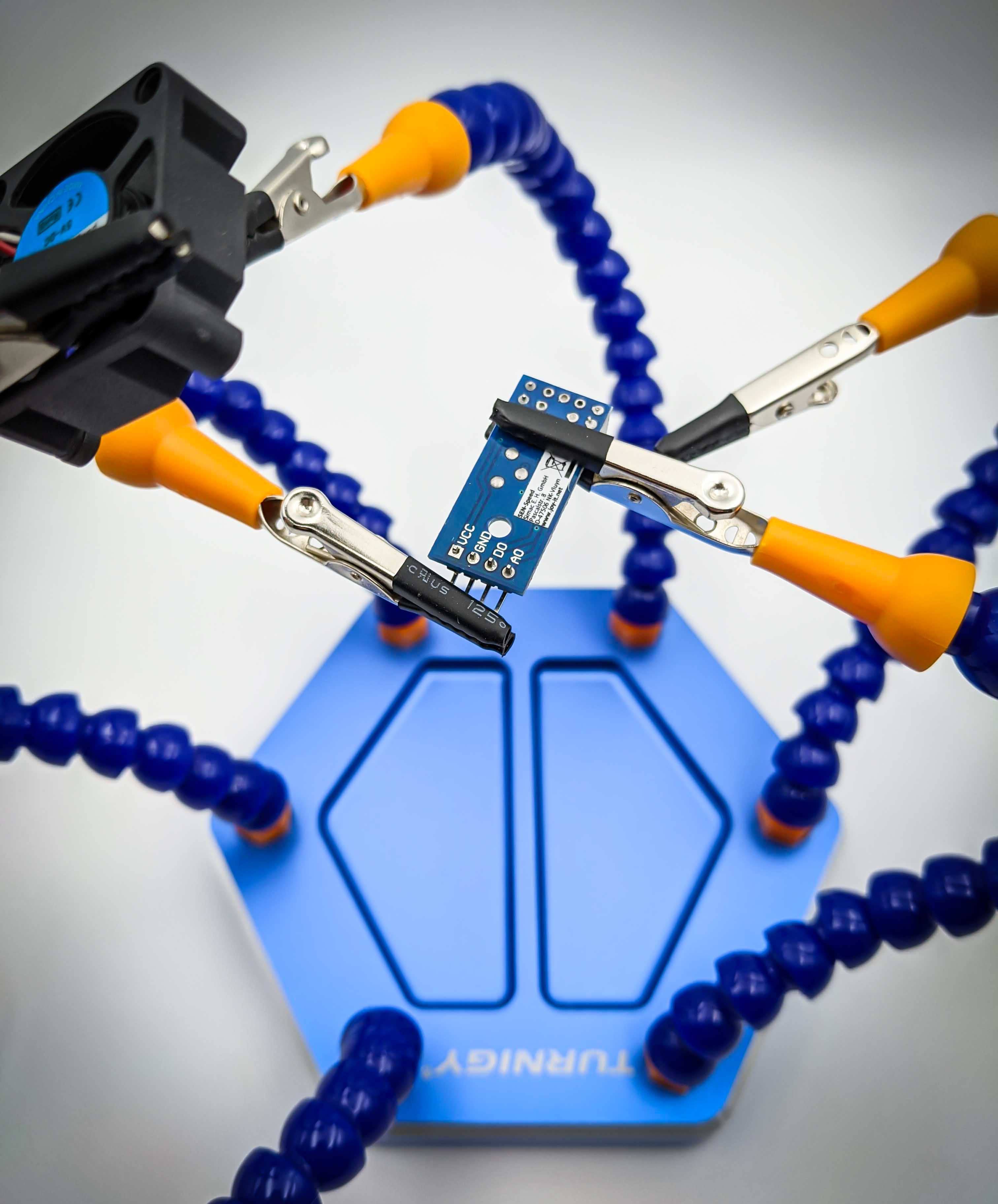
Speed Sensors
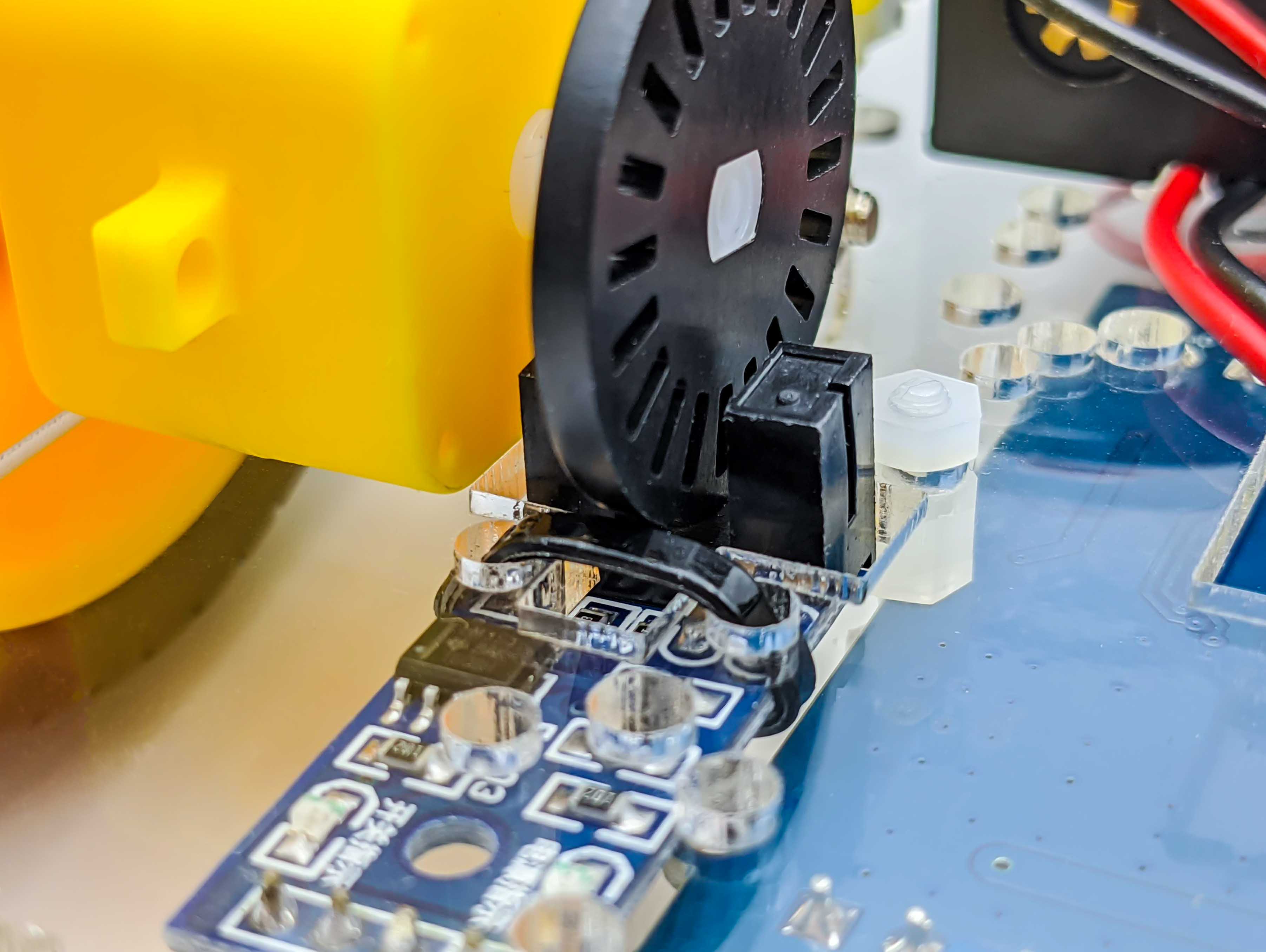
The LM393 speed sensor from Joy-IT has its pin header on the same side as the slot-type opto interrupter. I found that this makes it hard to mount these two sensors to the dedicated slots of the chassis so that the encoder wheel freely spins in the slot of the opto interrupter. Therefore I swaped the pin header to the other side of the speed sensor board. The following image shows the not so easy desoldering process:
With the pin headers swapped we use zip ties to fix the sensors to the slots of the acrylic chassis:
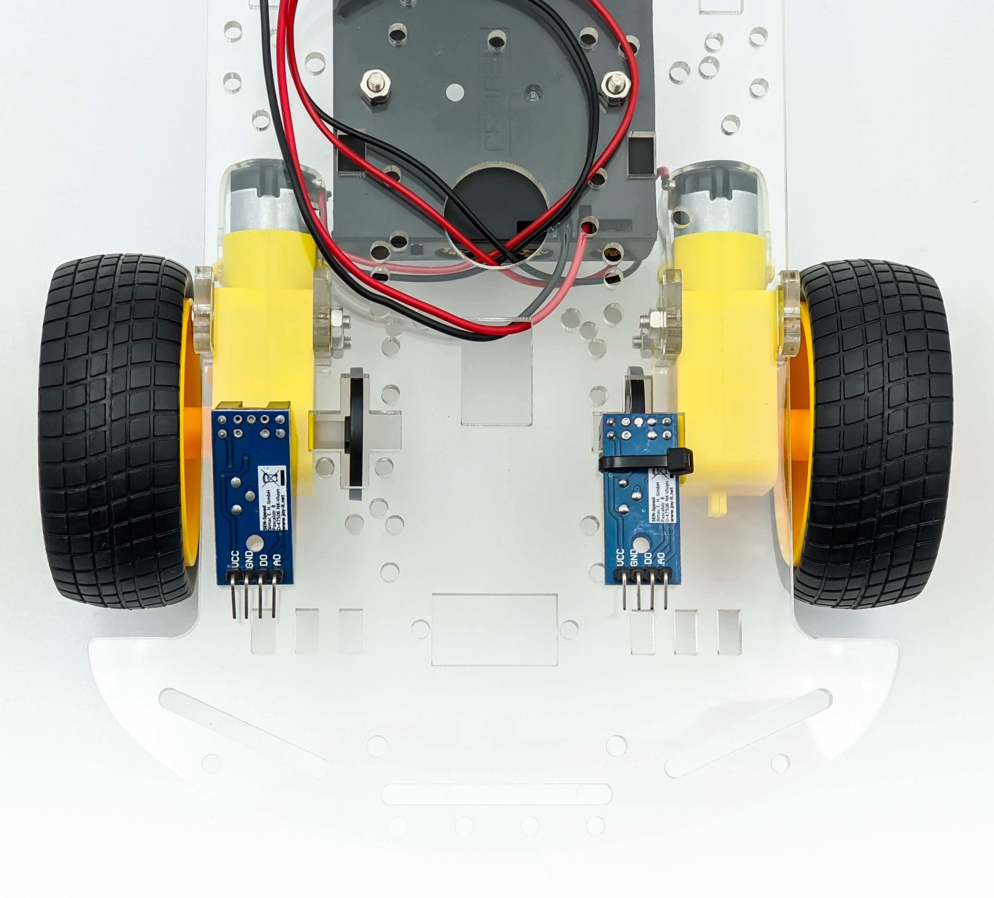
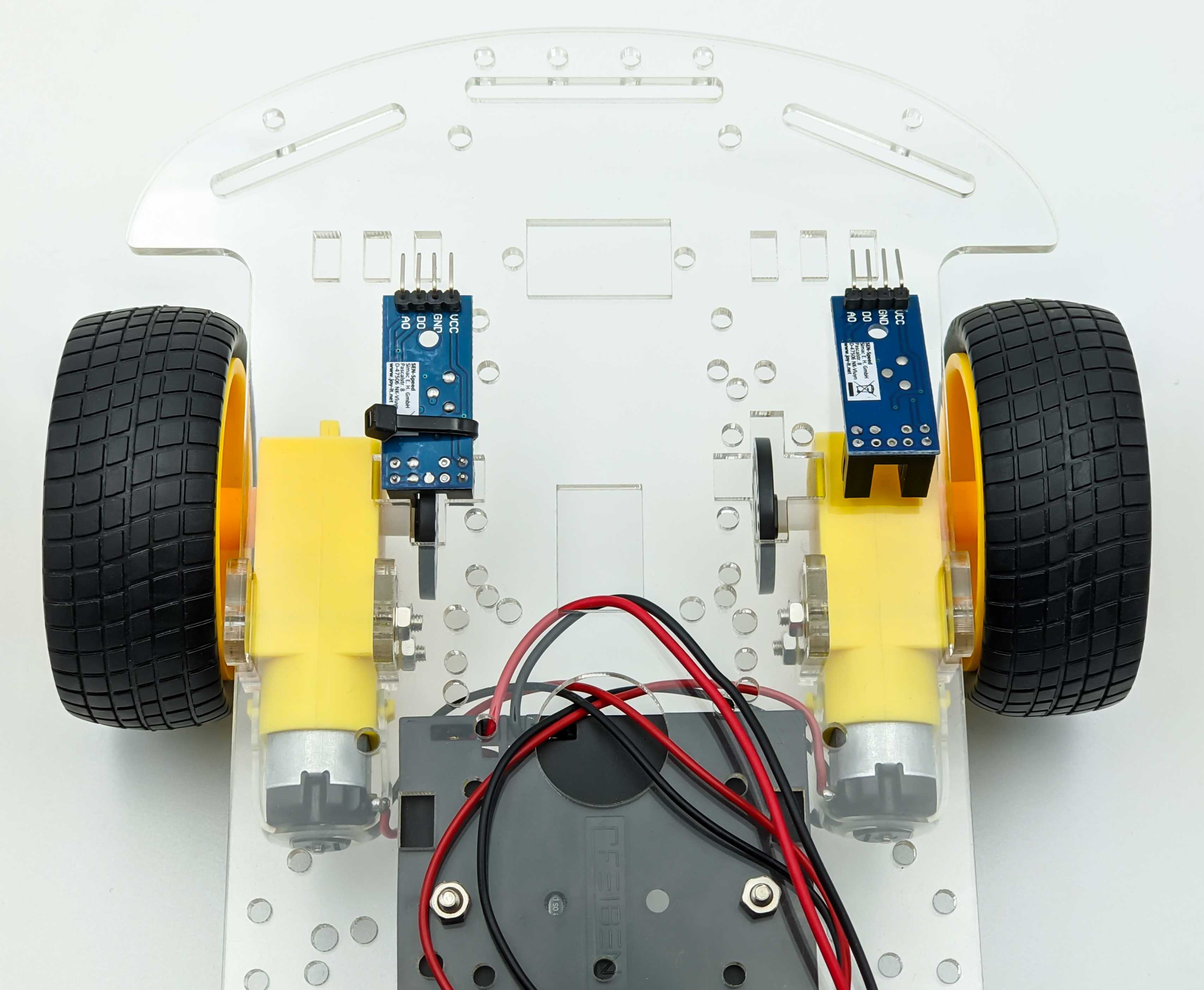
Here is the result after both speed sensors have been fixed with zip ties.
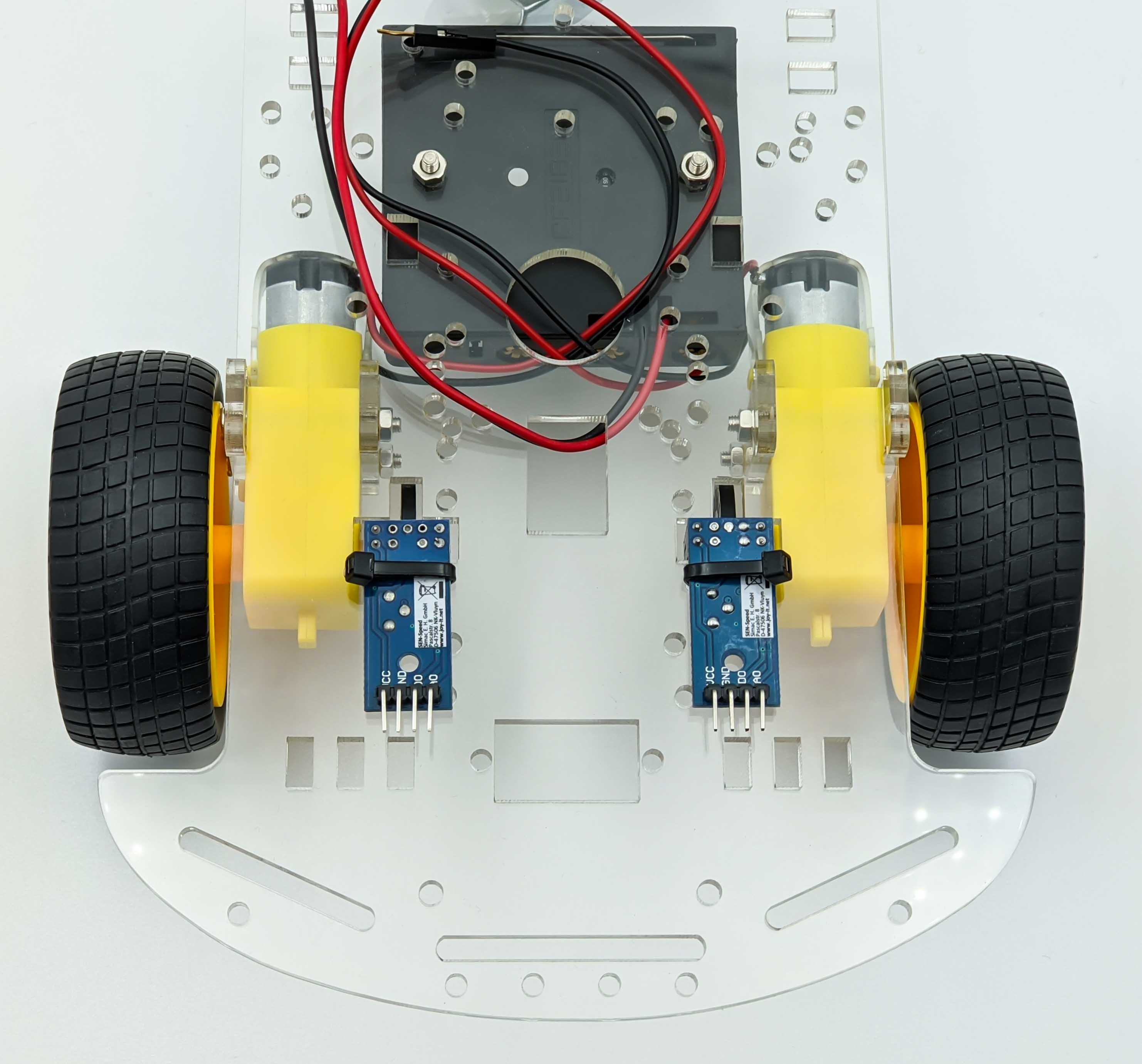
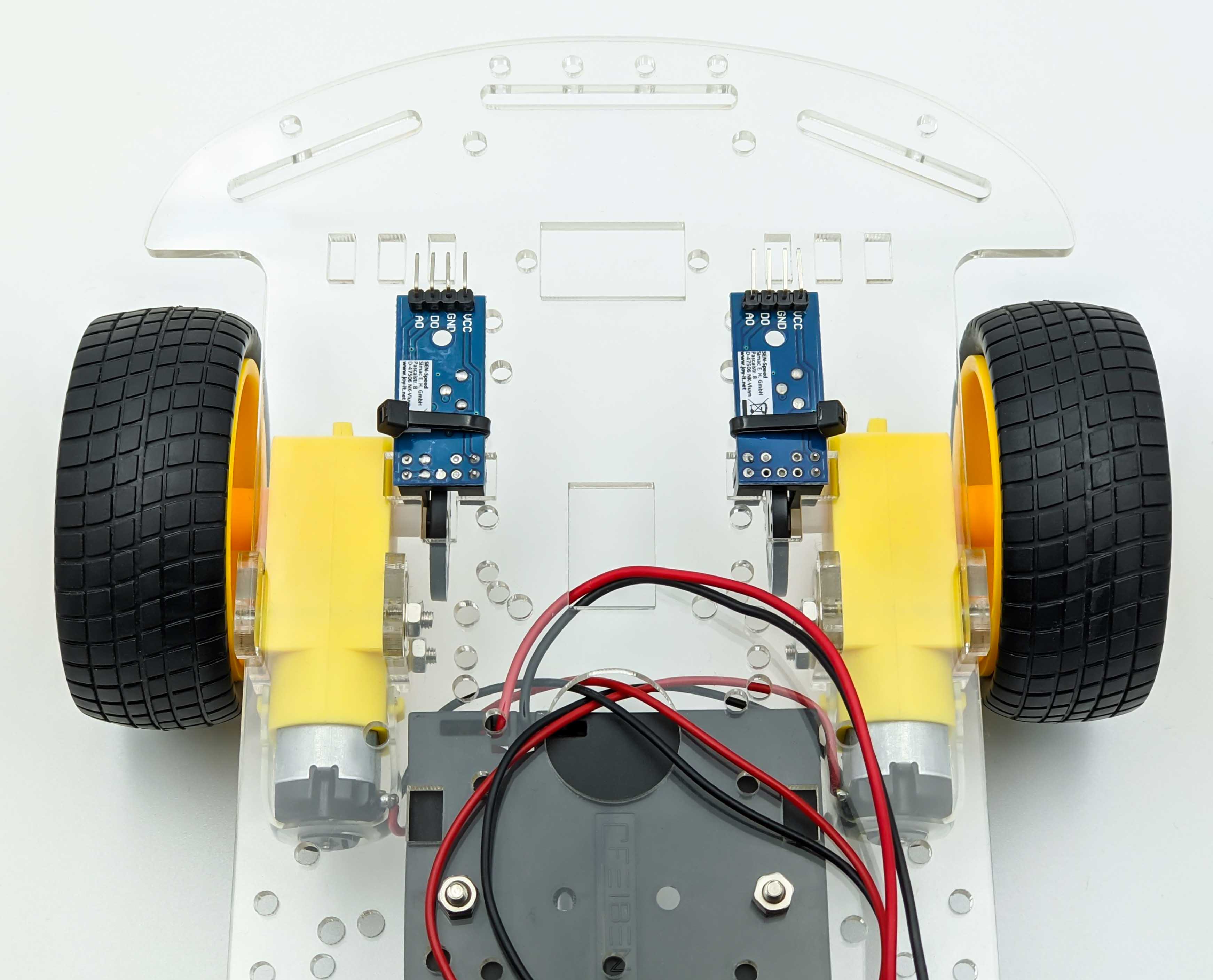
When using the zip ties, make sure that the encoder wheels spin freely and have no contact to the zip ties.
Motor Driver Mounting
To mount the motor driver we need to find suitable pre drilled holes. Alternatively we could drill new ones. For this build I use the available holes which you can see in the following images:
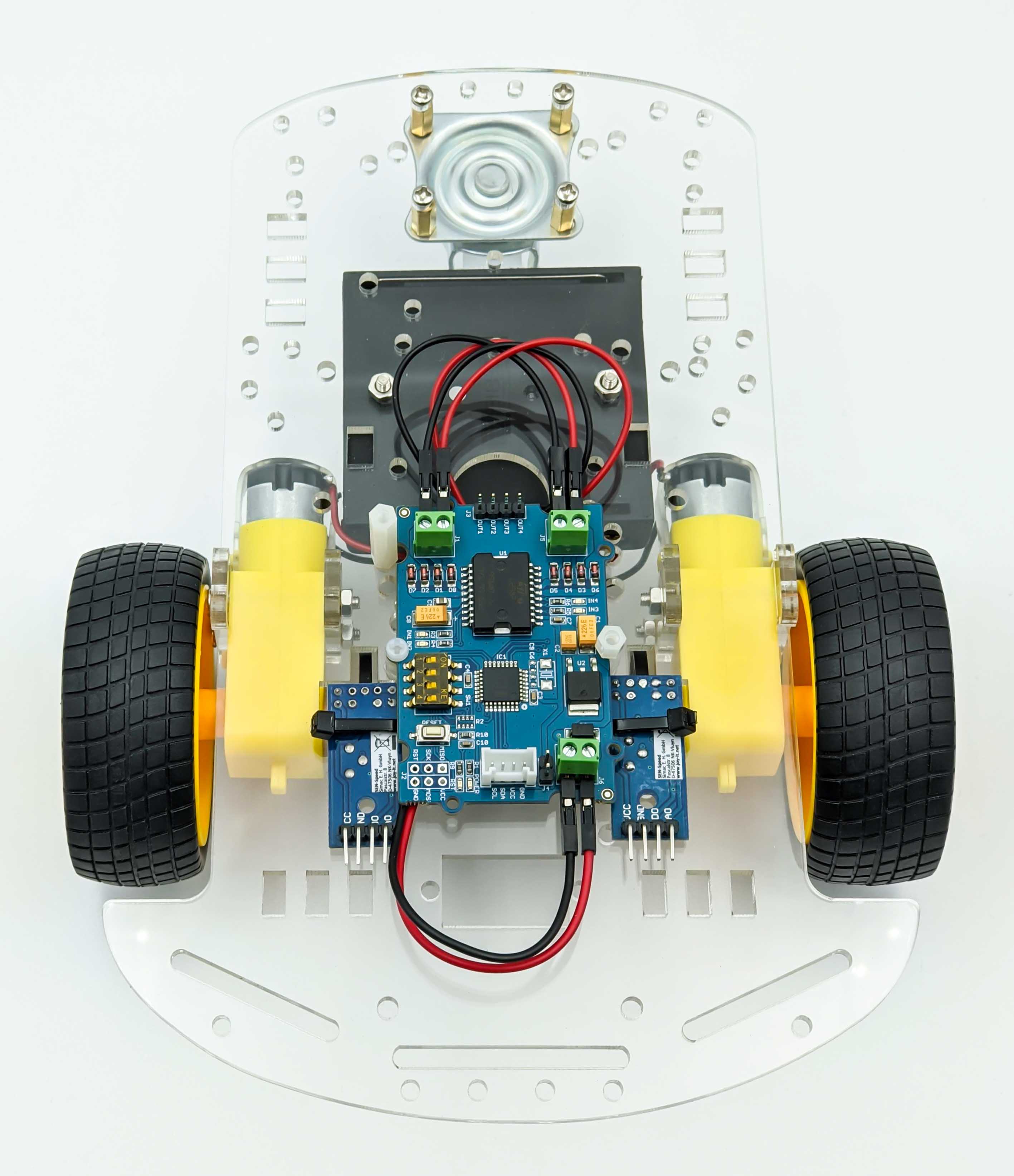
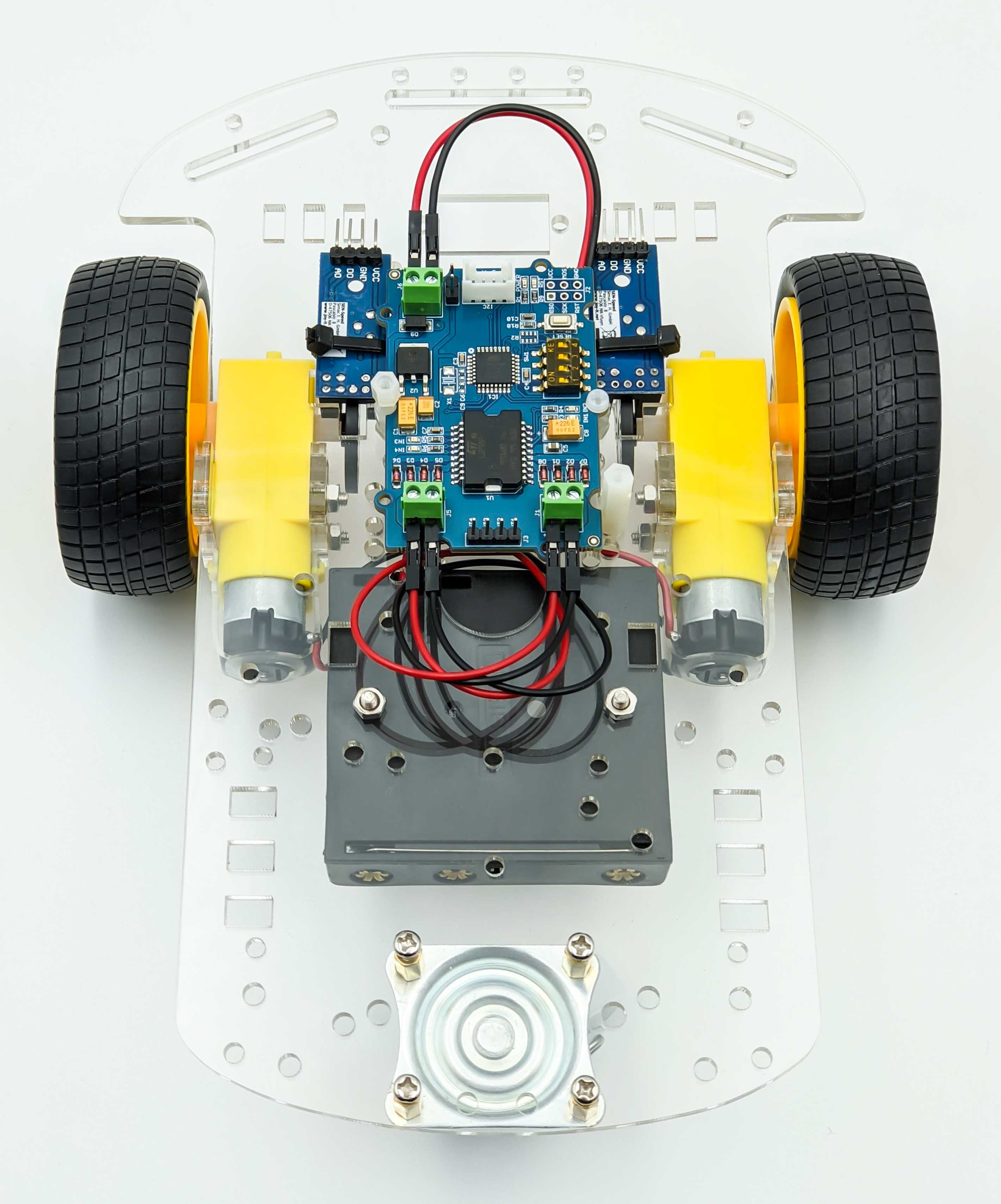
Here is the detailed location and screws used to fix the motor driver to the acrylic chassis base plate:
I2C Hub
The I2C Hub will be mounted in the front of the robot car using one zip tie and two free holes of the acrylic chassis.
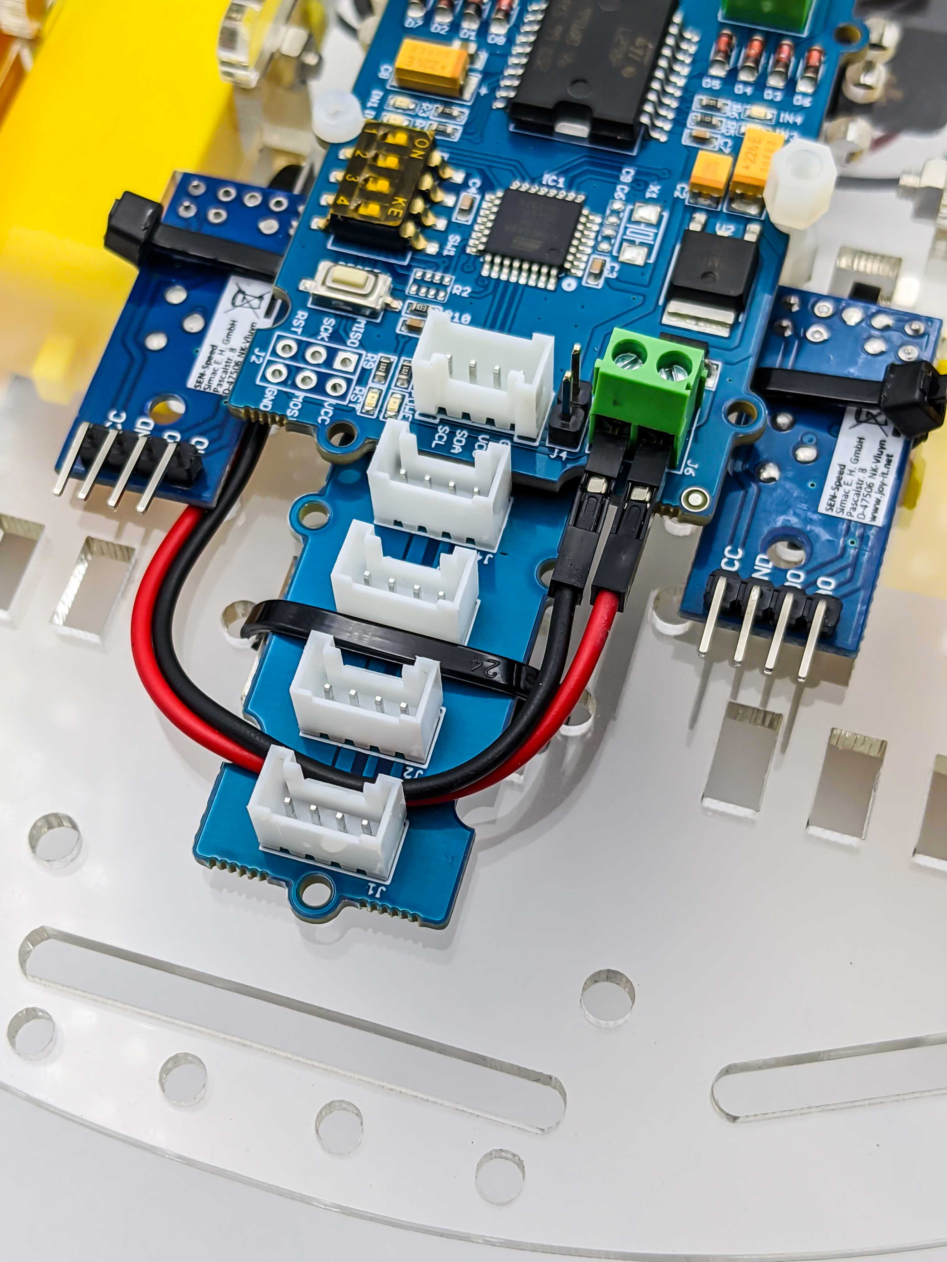
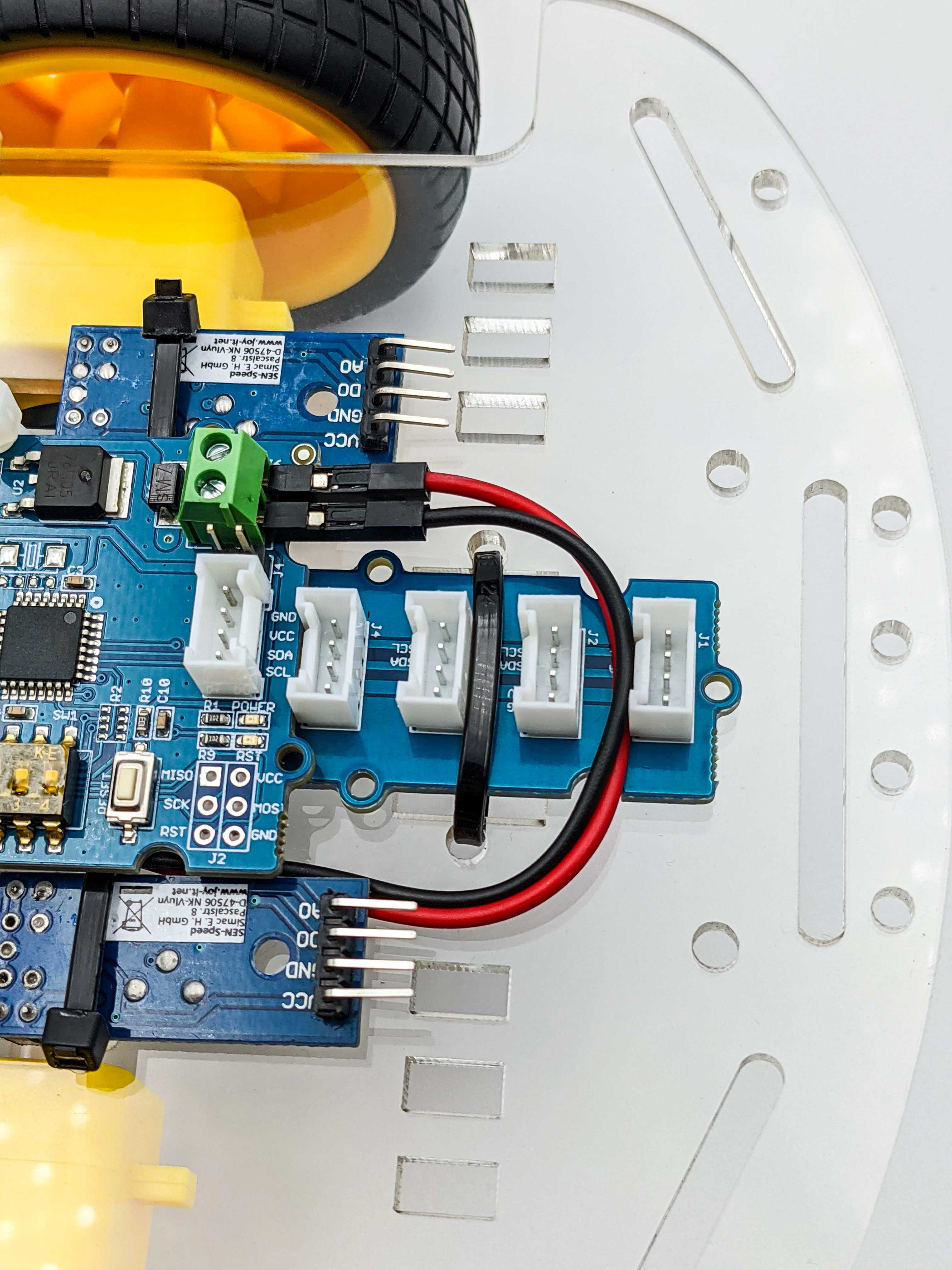
The following images show the holes used to zip tie the I2C hub.
Board Plate
The board plate which will be used to hold the Raspberry Pi 4 B is fixed with two plastic screws.
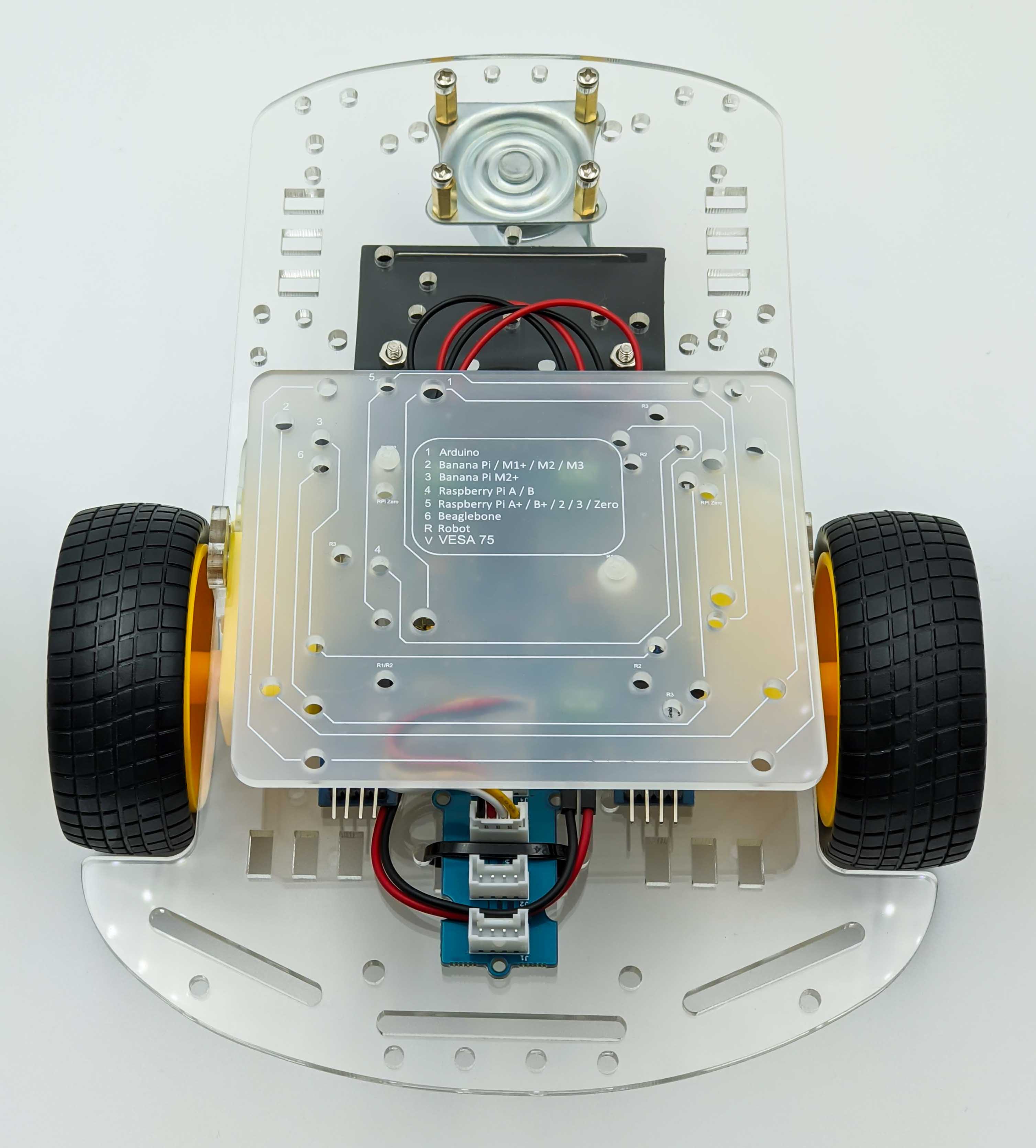
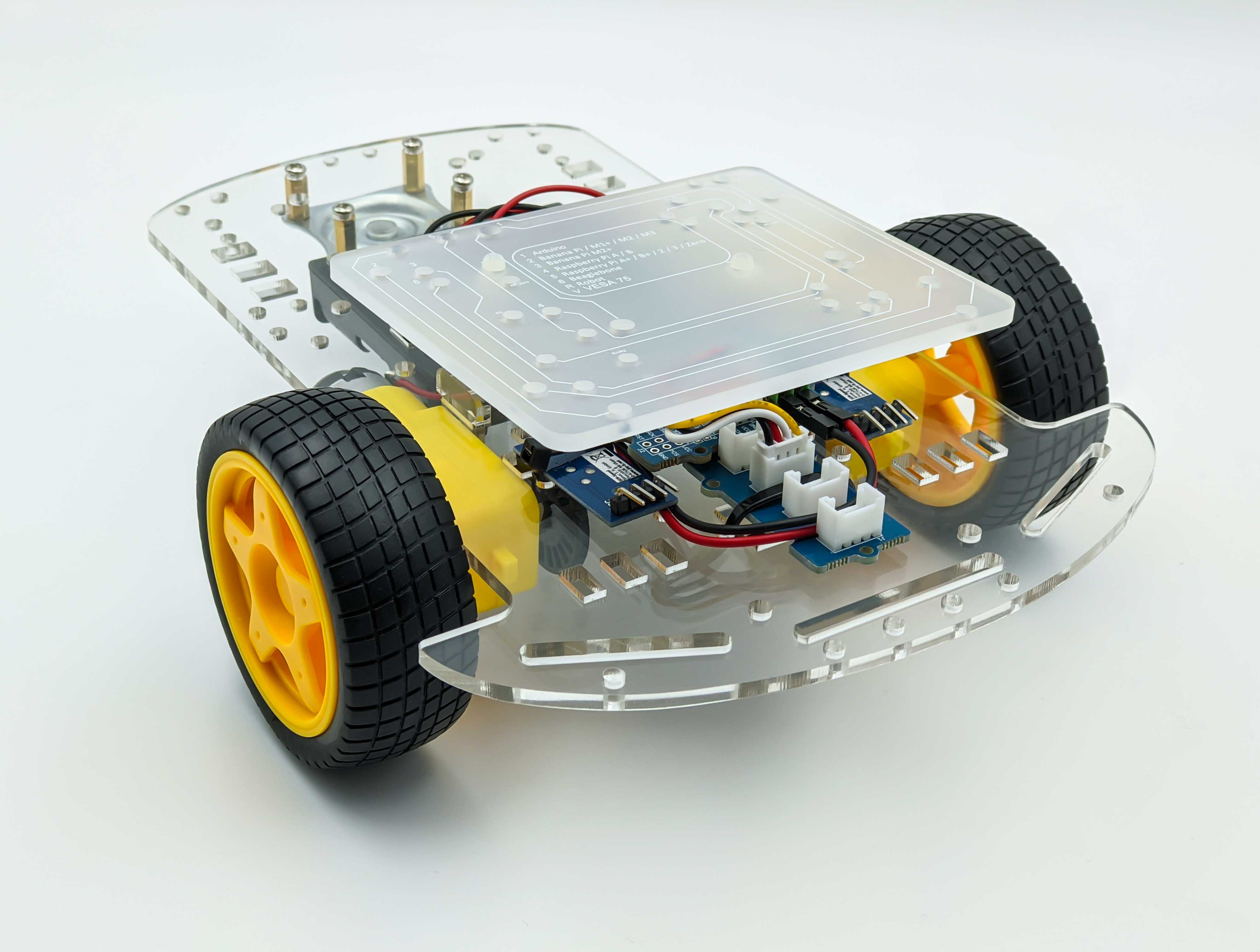
For the board mounting plate we will use a plastic distance piece.
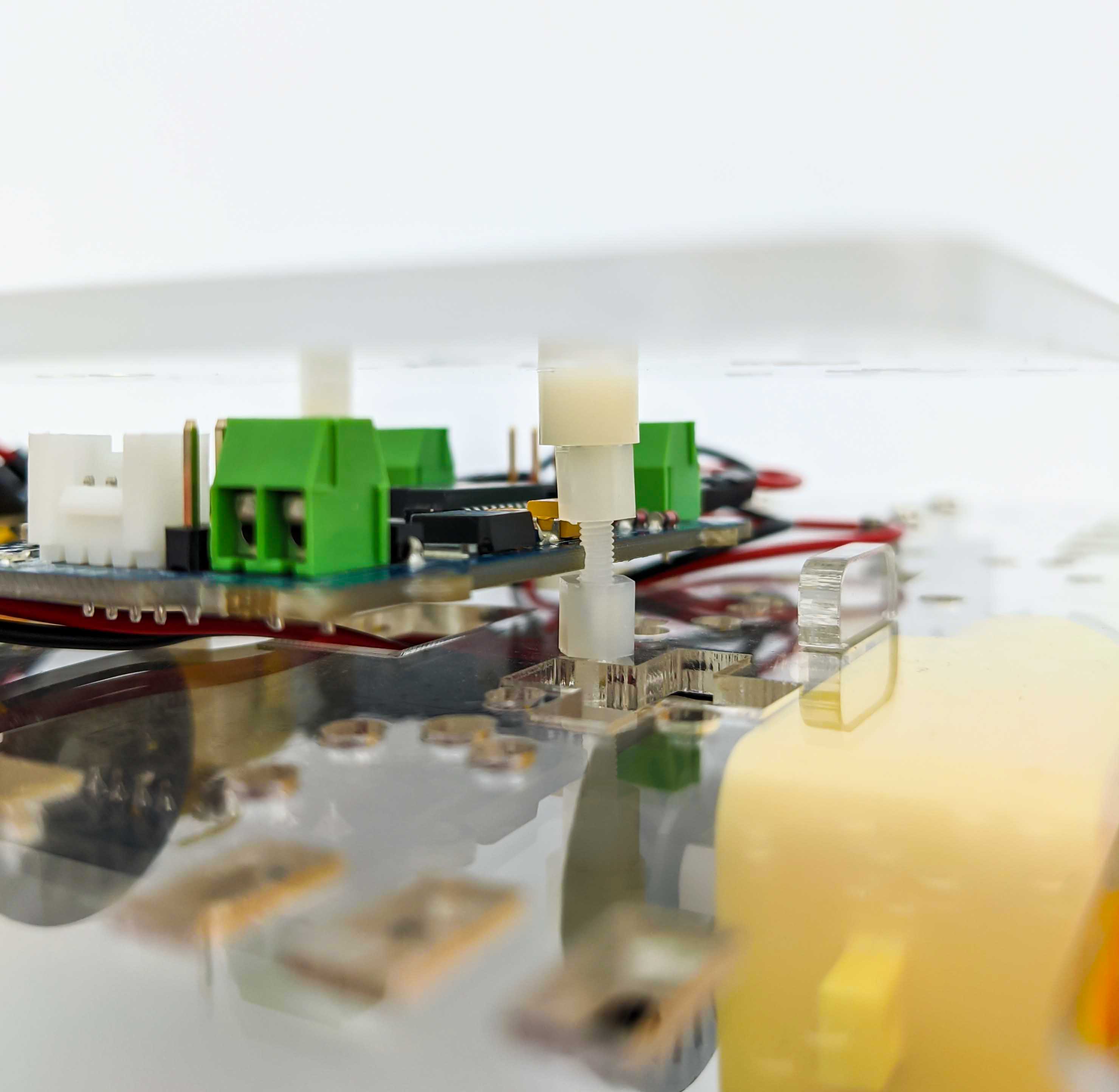
The following two images show the front of the mounted board plate. The motor driver is connected with short I2C cable to the I2C hub.
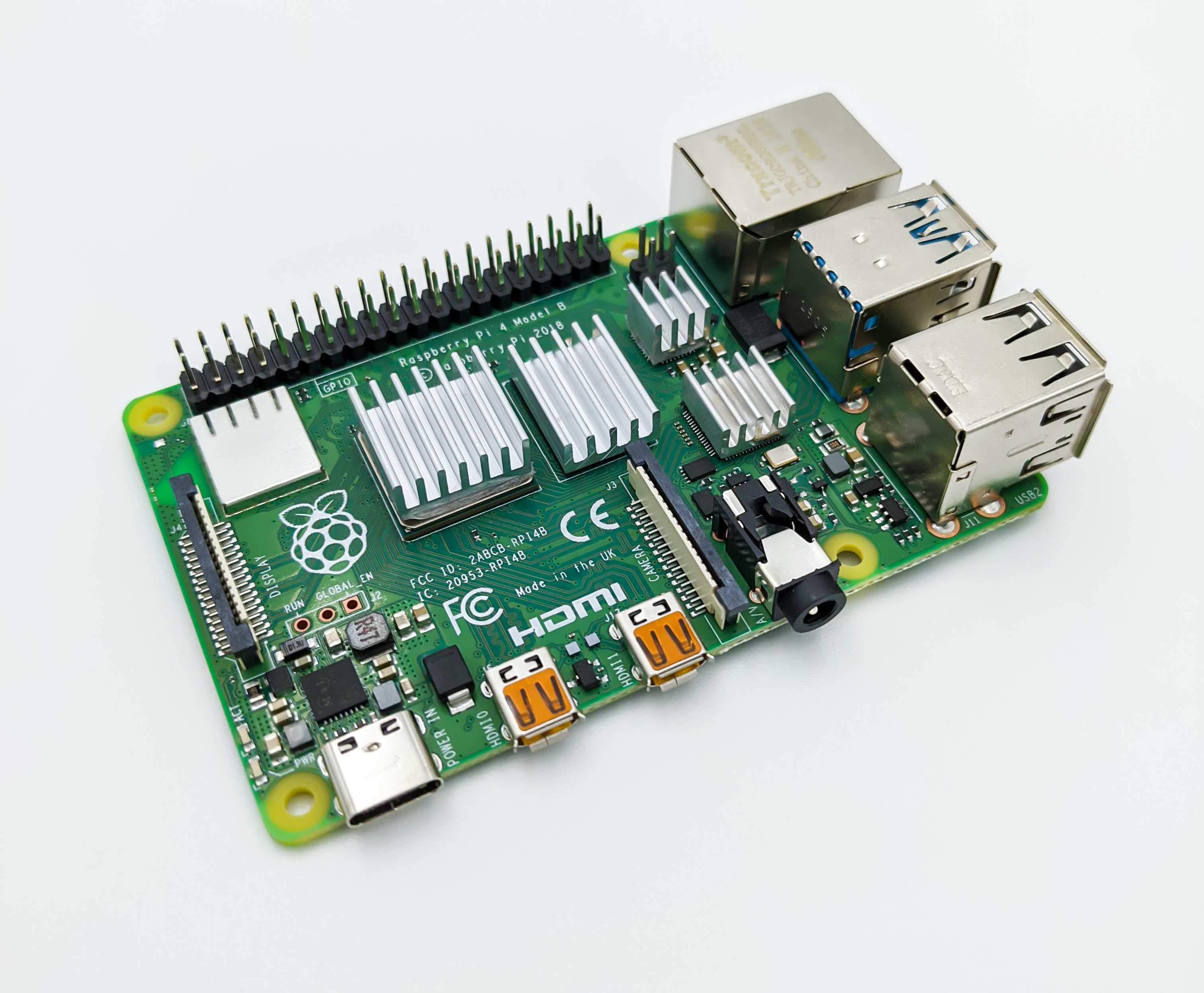
Cooling and Protecting the Raspberry Pi 4 B
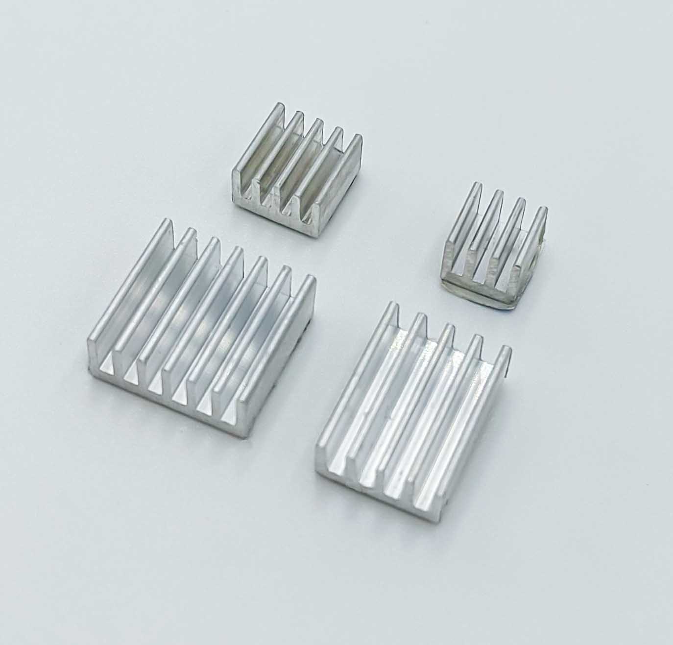
Because ROS requires a reasonable amount of computing power the processing unit of the Raspberry Pi 4 B can get quite hot. To avoid damaging the electronic components we apply four heatsinks and a cooling fan.
The cooling fan will be mounted to the case that will protect the Raspberry Pi 4 B. For this we use the acrylic rainbow case which is assembled by stacking the layers together with the Raspberry Pi in between.
Comments