Steps to Integrate a Robot into ROS
The steps to control a new robot using ROS are [1]:
- Decide on the ROS message interface.
- Write drivers for the robot’s motors.
- Write a model of the robot’s physical structure.
- Extend the model with physical properties for use in simulation with Gazebo.
- Publish coordinate transform data via
tfand visualize it withrviz. - Add sensors, with driver and simulation support.
- Apply standard algorithms, such as control and navigation.
ROS Message Interface
First we need to get control of the mobile base using a ROS node that communicates with the hardware and then presents a standard ROS interface to the rest of the system. Doing so follows a common and core concept of ROS: abstraction. Similar acting robots can reuse standard interfaces and thus take advantage of the large ROS ecosystem consisting of tools and libraries.
The defining characteristics of the 2WD robot are that it is mobile and driving on the ground. Its kinematic configuration is similar to a tricycle:
- translate forward and backward (along its x-axis)
- yaw (rotate about its z-axis)
- combinations of the two.
Because the robot is moving only in 2 dimensions, it cannot translate side to side (y-axis) or up and down (z-axis). Neither can it roll or pitch its body (rotation about its x- or y-axes, respectively).
To control it, we can make use of the geometry_msgs/Twist
(cmd_vel topic) message type interface. With this, the desired linear velocity vx along the x-axis (by convention,
positive is forward) and the rotational velocity vyaw about the z-axis (by convention, positive is counter-clockwise)
is sent as a command to the robot.
Using the rosmsg show command we can see what’s in the geometry_msgs/Twist message type:
fjp@ubuntu:~/git/ros_ws/src$ rosmsg show geometry_msgs/Twist
geometry_msgs/Vector3 linear
  float64 x
  float64 y
  float64 z
geometry_msgs/Vector3 angular
  float64 x
  float64 y
  float64 z
Some of the fields (specifically, linear/y, linear/z, angular/x, or angular/y) are not required for the 2WD robot and will therefore not be used.
To know how far the robot traveled, we expect to report its position and orientation in the plane as (x, y, yaw).
The ROS community uses the nav_msgs/Odometry (odom topic)
ROS message interface to receive the position and orientation as data from the robot.
fjp@ubuntu:~/git/ros_ws/src$ rosmsg show nav_msgs/Odometry
std_msgs/Header header
  uint32 seq
  time stamp
  string frame_id
string child_frame_id
geometry_msgs/PoseWithCovariance pose
  geometry_msgs/Pose pose
    geometry_msgs/Point position
      float64 x
      float64 y
      float64 z
    geometry_msgs/Quaternion orientation
      float64 x
      float64 y
      float64 z
      float64 w
  float64[36] covariance
geometry_msgs/TwistWithCovariance twist
  geometry_msgs/Twist twist
    geometry_msgs/Vector3 linear
      float64 x
      float64 y
      float64 z
    geometry_msgs/Vector3 angular
      float64 x
      float64 y
      float64 z
  float64[36] covariance
To report the robot’s position and orientation, we only really need to fill out the pose/pose/ position and
pose/pose/orientation fields, ignoring the covariance fields
(which are only needed for downstream components that reason about uncertainty).
Within pose/pose/position, we only need to fill out x and y.
Working with pose/pose/ orientation requires to construct a valid quaternion that represents a 3D orientation.
The field called header, of type std_msgs/Header, is contained in many ROS messages and contains important information for the correct interpretation of many types of data in a robot system:
- at what time the data was produced
- in what coordinate frame it is represented
We use these generic interfaces from ROS, as it allows us to used existing libraries and tools that can operate on these message types.
Hardware Driver
To control the 2WD robot and get its sensor information we will need interfaces to its hardware.
In this project the Raspberry Pi 4 B is used as the main processing unit.
It provides physical hardware interfaces such as GPIO pins, USB and a camera connector.
We will use these interfaces to connect the robots hardware components to the Raspberry Pi.
These interfaces operate on communication protocols where we can leverage existing libraries to work with these protocols.
For example the RPi.GPIO library provides methods to use the I2C protocol and
work with hardware interrupts. A more high level alternative would be the
gpiozero library created by Ben Nuttall
and is officially supported by Raspberry Pi Foundation.
Internally, this library makes use of RPi.GPIO and although it supports Python 2 we will start using
RPi.GPIO which provides all the required funcionality (e.g. reading from sensors and writing acuator commands)
in a way that is simple enough.
Another important aspect is to use the hardware interface to convert between the robot’s native representation of commands and data and the interfaces that ROS supports. Here we need to consider which existing ROS packages we are going to use and what types of message interfaces they use. Then we can apply math to the raw hardware signals to bring it in a form that is suitable for the ROS message types.
In this project DiffBot has two motors which operate on a voltage level value applied to them. In combination with the wheel encoder ticks, these values need to be brought into a “ROS format”. Specifically, ROS uses the notion of joints (revolute, rotational, continuous, …) with standard units for different pysical quantities, such as position (m), velocity (m/s), angle (rad), and angular velocity (rad/s).
Modeling the Robot: URDF and xacro
To integrate a robot into ROS we have to design a model of it using CAD tools (e.g. AutoCAD, SOLIDWORKS, Blender). This step is important for the following reasons. For example, we can use this model to simulate and control the robot, visualize it, or use ROS tools to get information on the robotic structure and its kinematics [2].
ROS has a standard meta package for designing and creating robot models called robot_model, which consists of a set of packages, some of which are called urdf, kdl_parser, robot_state_publisher, and collada_urdf. These packages help us create the 3D robot model description with the exact characteristics of the real hardware.
Note that the package robot_model is deprecated in ROS melodic and should not be used directly as dependency.
Instead, use the packages contained within the robot_model meta package.
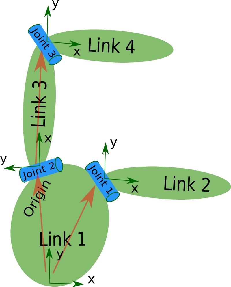
We can only describe a robot in URDF that has a tree-like structure in its links, that is, the robot will have rigid links and will be connected using joints. Flexible links can’t be represented using URDF. The URDF is composed using special XML tags, and we can parse these XML tags using parser programs for further processing. In our example, the chassis is the root, with connections to each of the rear wheels and the front caster, which in turn is connected to the front wheel. In fact,
joint_state_publisher: This package contains a node calledjoint_state_publisher, which reads the robot model description, finds all joints, and publishes joint values to all nonfixed joints using GUI sliders. The user can interact with each robot joint using this tool and can visualize using RViz. While designing URDF, the user can verify the rotation and translation of each joint using this tool.robot_state_publisher: This package reads the current robot joint states and publishes the 3D poses of each robot link using the kinematics tree built from the URDF. The 3D pose of the robot is published as the tf (transform) ROS. The tf ROS publishes the relationship between the coordinates frames of a robot.xacro: Xacro (XML Macros) is an XML macro language. Withxacro, you can construct shorter and more readable XML files by using macros that expand to larger XML expressions. This makes it easier to maintain robot description files, increase their readability, and to avoid duplication in the robot description files.
Unified Robot Description Format (URDF)
A robot is modeled in URDF, where we have to create a file and write the relationship between each link and joint in the robot and save the file with the .urdf extension. A good introduction to URDF is this video from David Lu at
ROSCon 2012.
URDF can represent the kinematic and dynamic description of the robot, the visual representation of the robot, and the collision model of the robot.
The following XML tags are the commonly used URDF tags to compose a URDF robot model:
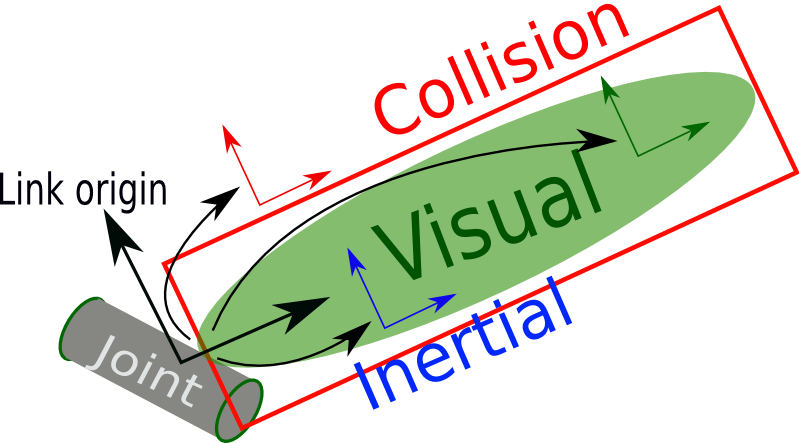
link: Thelinkelement describes a rigid body with a size and shape, visual features (color and 3D meshes), and dynamic features such as an inertial matrix and collision properties.
The syntax of the link tag is as follows:
<link name="<name of the link>">
  <inertial>...........</inertial>
  <visual> ............</visual>
  <collision>..........</collision>
</link>
The following figure shows a representation of a single link. It consists of a Visual section, which represents the real link of the robot and is visible in the simulation. For collision detection the link has a Collision section. The Collision section encapsulates the real link to detect collision before hitting the real link.
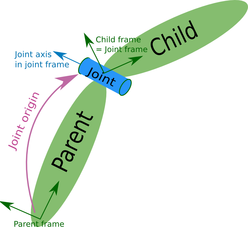
joint: Ajointconnects twolinks, the first is called the Parent link, and the second is called the Child link. The joint defines how the links can move with respect to each other. Describes the kinematic and dynamic properties of a joint, and set the limits of the joint movement and its velocity. Thejointtag supports the different types of joints, such as continuous, revolute, prismatic, planar, fixed and floating.
| Name | Description |
|---|---|
| continuous | A joint that can rotate indefinitely about a single axis |
| revolute | Like a continuous joint, but with upper and lower angle limits |
| prismatic | A joint that slides linearly along a single axis, with upper and lower position limits |
| planar | A joint that allows translation and rotation perpendicular to a plane |
| floating | A joint that allows full six-dimensional translation and rotation |
| fixed | A special joint type that allows no motion |
The syntax is as follows:
<joint name="<name of the joint>">
  <parent link="link1"/>
  <child link="link2"/>
  <calibration .... />
  <dynamics damping ..../>
  <limit effort .... />
</joint>
A URDF joint is formed between two links; The following is an illustration of a joint and its link:
robot: The root element in a robot description file must be arobot. It encapsulated the entire robot model that can be represented using URDF and includes all elements such aslink,joint,gazeboandtransmission.
gazebo: Thegazeboelement is an extension to the URDF robot description format, used to include the simulation parameters of the Gazebo simulator. This tag can be used to include for example gazebo plugins andgazebomaterial properties. The following shows an example usinggazebotags:
<gazebo reference="link_1">
  <material>Gazebo/Black</material>
</gazebo>
It will be important for the simulation with Gazebo that your robot description contains collision and inertia parameters in each link, otherwise Gazebo will not load the robot model properly (see also the related urdf tutorial.
The difference between base_link and base_footprint is defined in REP-120.
xacro
The xacro package helps to reduce the overall size of a robot description which makes it easier to read and maintain the robot description. For this, xacro provides the following:
- Simplify URDF: xacro is the cleaned-up version of URDF. With it you can create macros inside the robot description and reuses them which reduces the xacro description length of your robot. Also, it can include macros from other files and make the code simpler, more readable, and more modular.
- Programmability: The xacro language supports simple programming statements in its description. There are variables, constants, mathematical expressions, conditional statements, which make the description more intelligent and efficient.
In the end, most ROS packages still require a URDF description, which can be generated from the compact xacro description in the following ways. Either you use the command
xacro --inorder model.xacro > model.urdf
or create a launch file with the following content:
<param name="robot_description" command="xacro --inorder '$(find pr2_description)/robots/pr2.urdf.xacro'" />
Tools for Verification and Visualization
The following two tools can be installed with sudo apt install liburdfdom-tools.
The check_urdf command will parse the urdf tag and show an error, if there are any. If everything is OK, it will output a success message followed by the robot description.
To view the structure of the robot links and joints graphically, we can use a command tool called urdf_to_graphiz.

The simplest way to visualize and to test manipulate the robot in RViz is to
create a launch file similar to the following example. Note that the ROS urdf tutorials use the deprecated use_gui parameter and the joint_state_publisher package instead of the new joint_state_publisher_gui package, which includes the slider gui and doesn’t require the use_gui parameter:
<launch>
  <arg name="model" default="$(find urdf_tutorial)/urdf/01-myfirst.urdf"/>
  <arg name="rvizconfig" default="$(find urdf_tutorial)/rviz/urdf.rviz" />

  <param name="robot_description" command="$(find xacro)/xacro $(arg model)" />

  <node name="joint_state_publisher_gui" pkg="joint_state_publisher_gui" type="joint_state_publisher_gui" />
  <node name="robot_state_publisher" pkg="robot_state_publisher" type="robot_state_publisher" />
  <node name="rviz" pkg="rviz" type="rviz" args="-d $(arg rvizconfig)" required="true" />
</launch>
With this launch file you can pass two command line arguments model and rvizconfig to the roslaunch command, where each has its default value and can be omitted. The launch files uses xml parameter tag which sets up the robot description parameter on the parameter server:
robot_description: load URDF data from a file to the parameter server. To load the URDF data there are three different methods:
- Use
<param>with thecommandattribute, as shown in this URDF tutorial. - Use
<param>with the<textfile>argument as shown here which is commonly used when not working withxacro. - Use
<param>with thecommandattribute and thexacroscript, as shown in the very first example on the Xacro tutorial page.
Note that you will see some launch files which include a use_gui parameter.
This is deprecated in ROS Melodic Morenia. It is used in older ROS distributions and is a bool value used
to show the gui that comes with the older version of joint_state_publisher.
The rest of the launch file loads three nodes:
joint_state_publisher_guiused to manipulate joint states with the optional gui (depending ifjoint_state_publisher_guior justjoint_state_publisheris launched) and to read current joint states using asource_listparameter (not used in this example).robot_state_publisherpackage helps to publish the state of the robot totf. This package subscribes to joint states of the robot and publishes the 3D pose of each link using the kinematic representation from the URDF model. This is required for packages such as visualization.rvizused to visualize the robot. In the launch file a rviz configuration is loaded, which takes the burden of configuring RViz manually after each startup.

As you move the sliders around in the GUI of joint_state_publisher_gui,
the joints and links of the model move in RViz. How is this done? First the GUI parses the URDF and finds all the non-fixed joints and their limits. Then, it uses the values of the sliders to publish sensor_msgs/JointState messages.
Those are then used by robot_state_publisher to calculate all of transforms between the different parts. The resulting transform tree is then used to display all of the shapes in Rviz.
Simulation in Gazebo
To visualise a robot in RViz and use the nodes described so far, the URDF should contain the robot’s kinematic description.
This is done by defining <visual> and <origin> tags in the <link> elements and connecting the links using <joint> tags.
To simulate a robot in ROS using Gazebo the URDF requires dynamic information. For this,
some additional simulation-specific elements must be added to work properly with the Gazebo physics engine.
The <inertia> element must be provided within each <link> element.
Determining the correct inertia values for each link is required to get accurate physics approximations in Gazebo.
This can be performed by conducting various measurements of the robots parts, using CAD software like Solidworks that includes features for approximating these values or use precalcuated values from a list of moments of inertia for simple shapes.
<inertial>
  <origin xyz="0 0 ${height1/2}" rpy="0 0 0"/>
  <mass value="1"/>
  <inertia
      ixx="1.0" ixy="0.0" ixz="0.0"
      iyy="1.0" iyz="0.0"
      izz="1.0"/>
</inertial>
The origin tag represents the center of mass of this link. Within Gazebo it is possible to visually check if the center of mass is correct in a URDF by clicking on the “View” menu of Gazebo and selecting both “Wireframe” and “Center of Mass”.
Unlike some ROS applications, Gazebo will not use the <visual> elements as collision information.
Instead, Gazebo will treat your link as “invisible” to laser scanners and collision checking.
To properly handle collisions in Gazebo a <collision> element must be added to each <link> which should resemble the
<visual> element. For performance reasons a simplified model/mesh should be used as collision geometry.
The optional <gazebo> element is an extension to the URDF used for specifying additional properties needed for simulation purposes in Gazebo. If no <gazebo> element are provided, default values will be automatically included. There are three different types of <gazebo> elements - one for the <robot> tag, one for <link> tags, and one for <joint> tags.
- Add a
<gazebo>element for every<link>- Convert visual colors to Gazebo format
- Convert stl files to dae files for better textures
- Add sensor plugins
- Add a
<gazebo>element for every<joint>- Set proper damping dynamics
- Add actuator control plugins
- Add a
<gazebo>element for the<robot>element - Add a
<link name="world"/>link if the robot should be rigidly attached to the world/base_link
URDF can only specify the kinematic and dynamic properties of a single robot in isolation. URDF can not specify the pose of the robot itself within a world. It is also not a universal description format since it cannot specify joint loops (parallel linkages), and it lacks friction and other properties. Additionally, it cannot specify things that are not robots, such as lights, heightmaps, etc.
To deal with this issue, a new format called the Simulation Description Format (SDF) was created for use in Gazebo to solve the shortcomings of URDF. SDF is a complete description for everything from the world level down to the robot level. It is scalable, and makes it easy to add and modify elements. The SDF format is itself described using XML, which facilitates a simple upgrade tool to migrate old versions to new versions. It is also self-descriptive. Under the hood, Gazebo will convert the URDF to SDF automatically.
Many .world files are distributed as part of the gazebo9-common debian package, which can be found in /usr/share/gazebo-9/worlds, including empty.world (see this answer). The following xml snippet shows the content of the empty.world world file:
<?xml version="1.0" ?>
<sdf version="1.5">
  <world name="default">
    <!-- A global light source -->
    <include>
      <uri>model://sun</uri>
    </include>
    <!-- A ground plane -->
    <include>
      <uri>model://ground_plane</uri>
    </include>
  </world>
</sdf>
Everything concerning a robot’s model and description should be located, as per ROS standards, in a package named /MYROBOT_description and all the world files and launch files used with Gazebo is located in a ROS package named /MYROBOT_gazebo. In this project 'MYROBOT' is replaced with the name of this robot ('diffbot') in lower case letters.
If no special world is required then the /MYROBOT_gazebo/world folder is not required and default worlds can be used.
Example world models can be launched from the command line:
roslaunch gazebo_ros empty_world.launch
One way to launch a robot inside a world is to use a launch file within the /MYROBOT_gazebo package which launches
empty_world.launch and spawns a robot model using the spawn_model python script.
This script is located within the gazebo_ros package and is used to make a service call request to the gazebo_ros ROS node (named simply “gazebo” in the rostopic namespace) to add a custom URDF into Gazebo, see gazebo tutorial.
<launch>
  <!-- Use logic from empty_world.launch, changing only the name of the world to be launched -->
  <include file="$(find gazebo_ros)/launch/empty_world.launch">
    <!-- arg name="world_name" value="$(find MYROBOT_gazebo)/worlds/MYROBOT.world"/ -->
    <!-- more default parameters can be changed here -->
  </include>

  <!-- Convert an xacro and put it on the parameter server -->
  <param name="robot_description" command="$(find xacro)/xacro.py $(find MYROBOT_description)/robots/MYROBOT.urdf.xacro" />

  <!-- Spawn a robot into Gazebo -->
  <node name="spawn_urdf" pkg="gazebo_ros" type="spawn_model" args="-param robot_description -urdf -model MYROBOT" />
</launch>
empty_world.launch will take care of launching the gazebo server and client with the specified parameters or their defaults.
The spawn_model script can be used in the following way:
rosrun gazebo_ros spawn_model -file `rospack find MYROBOT_description`/urdf/MYROBOT.urdf -urdf -x 0 -y 0 -z 1 -model MYROBOT
To see all of the available arguments for spawn_model including namespaces, trimesh properties, joint positions and RPY orientation run:
rosrun gazebo_ros spawn_model -h
To verify that a URDF can be properly converted to SDF use the following procedure.
First the .xacro model of the robot is converted into a .urdf, note that --inorder is not required when using ROS melodic.
xacro --inorder model.xacro > model.urdf
With Gazebo installed, an easy tool exists to check if a URDF can be properly converted into a SDF.
gz sdf -p model.urdf
This will print out the SDF that has been generated from the input URDF as well as any warnings about missing information required to generate the SDF.
After resourcing the catkin workspace, the created launch file can be launched with:
. ~/catkin_ws/devel/setup.bash
roslaunch MYROBOT_gazebo MYROBOT.launch
This will open Gazebo and spawn the robot model in an empty world.
To control a model in Gazebo using ROS there exist plugins that are declared in the URDF which will then get loaded. See the list of plugins that are already available. Here you will for example find plugins for sensors.
Especially important is the gazebo_ros_control plugin, for a tutorial to integrate this see here.
References
- Tutorial: Using roslaunch to start Gazebo, world files and URDF models
- Tutorial: Using a URDF in Gazebo
Verifying Transforms
Publish coordinate transform data via tf and visualize it with rviz.
Adding Sensors and Actuators in ROS
To integrate new sensors and actuators into the ROS ecosystem with driver and simulation support, involves writing ROS wrappers around the APIs used to access these devices.
Adding Sensors
If a sensor already has a Python API it is relatively straightforward to use sensors in ROS. First you should always verify that things are working as expected before you start to wrap up a sensor in ROS. If you know that the sensor is working, then anything that goes wrong will be a problem with the ROS wrapper, which will make things easier to debug.
In ROS there are two ways to work with sensor data. One way is that the sensor publishes topics which other nodes can subscribe to. Another way is that the sensor node provides measurments only when asked for using either a service or action call which other nodes can use and thereby act as clients. This decision depends on how we are going to use the sensor.
Another decision to make is how we’re going to access data from the sensor, which depends on the sensor.
Finally we need to decide what type of ROS message our wrapper will produce. Whenever possible we should use existing ROS message types because it allows us to reuse the wrapped sensor with other nodes that use the same interface types.
Adding Actuators
Utilizing and Configuring Existing ROS Packages
Apply standard algorithms, such as control and navigation.
ROS Control
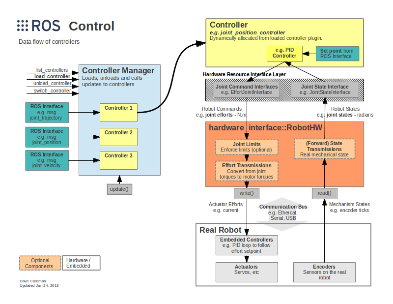
The ros_control repositories provide agnostic controllers of different type, such as the diff_drive_controller,
that allow us to interact over a gerneric hardware interface. For a concise introduciton to ros_control, read this ROS Control overview post, which is a summary of the ROSCon 2014 talk from Adolfo Rodríguez Tsouroukdissian.
The steps to use the diff_drive_controller, (repository on GitHub) are:
- Install
ros_controlon Ubuntu from the Debian packages (recommended):
sudo apt-get install ros-melodic-ros-control ros-melodic-ros-controllers
- URDF File
- YAML Files
- Write a hardware interface: ROS Tutorial, Slaterobots blog post, ros_control_boilerplate from Dave Coleman, eborghi10/my_ROS_mobile_robot using Joint Command Interface and Joint State Interface as these are required for the
diff_drive_controller.
The following image from the ros_control wiki shows the structure of ROS control.
ROS Navigation
To enable navigating the robot around in an environment a meta package commonly known as navigation stack is often used in ROS. Follow also this tutorial to setup the navigation stack on a robot.
Using rviz to Localize and Command a Navigating Robot
References
Programming Robots with ROS A Practical Introduction to the Robot Operating System
Comments