ROS Control Package for ROS Melodic running on a Raspberry Pi 4 for an autonomous 2WD Robot to act in an environment according to sensor information.
DiffBot Control Package
As described in the ROS Integration and
Gazebo Simulation sections,
DiffBot makes use of ROS Control repositories.
Specifically the diff_drive_controller package from the
ros_controllers meta package.
To leverage ROS Control for the simulation with Gazebo the robot description and the
controller configuration (usually a MYROBOT_control.yaml file) is required. For the real hardware its required to implement
a class derived from hardware_interface::RobotHW.
The convention to control a robot (in simulation and in the real world) is to have a package named MYROBOT_control. In case of DiffBot its called diffbot_control and created with
catkin create pkg PKG_NAME [--catkin-deps [DEP [DEP ...]]]:
catkin create pkg diffbot_control --catkin-deps diff_drive_controller roscpp sensor_msgs
Creating package "diffbot_control" in "/home/fjp/git/diffbot/ros/src"...
Created file diffbot_control/CMakeLists.txt
Created file diffbot_control/package.xml
Created folder diffbot_control/include/diffbot_control
Created folder diffbot_control/src
Successfully created package files in /home/fjp/git/diffbot/ros/src/diffbot_control.
To work with this package the specified dependencies must be installed either using the available Ubuntu/Debian packages for ROS Noetic or have to be built from source first. The following table lists the dependencies that we have to install because they are not already part of the ROS Noetic desktop full installation. Refer to the section ROS Noetic Setup for how this was done.
| Dependency | Source | Ubuntu/Debian Package |
|---|---|---|
diff_drive_controller |
https://github.com/ros-controls/ros_controllers | ros-noetic-ros-controllers |
To install a package from source clone (using git) or download the source files from where they are located (commonly hosted on GitHub) into the src folder of a ros catkin workspace and execute the catkin build command. Also make sure to source the workspace after building new packages with source devel/setup.bash.
cd /home/fjp/git/diffbot/ros/  # Navigate to the workspace
catkin build              # Build all the packages in the workspace
ls build                  # Show the resulting build space
ls devel                  # Show the resulting devel space
Make sure to clone/download the source files suitable for the ROS distribtion you are using. If the sources are not available for the distribution you are working with, it is worth to try building anyway. Chances are that the package you want to use is suitable for multiple ROS distros. For example if a package states in its docs, that it is only available for kinetic it is possible that it will work with a ROS noetic install.
ROS Control in Gazebo
Two great resources to get the diff_drive_controller working inside Gazebo is the Gazebo ROS Control Tutorial
of rrbot and the R2D2 ROS URDF Tutorial, especially the last section, The Wheels on the Droid Go Round and Round.
To spawn DiffBot inside Gazebo, RViz and control it with the rqt_robot_steering plugin,
launch the diffbot.launch inside the diffbot_control package:
roslaunch diffbot_control diffbot.launch
This launch file makes use of diffbot_gazebo/launch/diffbot.launch, diffbot_control/launch/diffbot_control.launch to run gazebo and the diff_drive_controller. It also opens RViz with the configuration stored in diffbot_control/rviz/diffbot.rviz.
The following video shows the result of launching. Note the video may be outdated when you read this and the model has improved.
ROS Control on the Real Hardware
As mentioned above the its required to implement a class derived from
hardware_interface::RobotHW.
Let’s call it DiffBotHW and create it inside the diffbot_control/src folder.
Grove - I2C Motor Driver V1.3
The package for the Grove I2C Motor Driver V1.3 from Seeed Studio is created with catkin create pkg PKG_NAME [--catkin-deps [DEP [DEP ...]]]:
fjp@ubuntu:~/git/diffbot/ros/src$ catkin create pkg grove_motor_driver --catkin-deps rospy roscpp geometry_msgs
Creating package "grove_motor_driver" in "/home/fjp/git/diffbot/ros/src"...
Created file grove_motor_driver/CMakeLists.txt
Created file grove_motor_driver/package.xml
Created folder grove_motor_driver/include/grove_motor_driver
Created folder grove_motor_driver/src
Successfully created package files in /home/fjp/git/diffbot/ros/src/grove_motor_driver.
The package depends on the two ROS client libraries rospy and roscpp.
To control the two motors the package will use the geometry_msgs/Twist message.
The interface to the motor driver is done with the Python library from DexterInd
which is a rewerite of the Seeed Studio Arduino library.
This library requires the following two python libraries
These libraries should be installed with pip3, Python’s package manager:
pip3 install RPi.GPIO
pip3 install smbus
Note that this will install these packages system wide. This is ok because they are installed on the Raspberry Pi which is dedicated to
operate for this purpose. For a development environment it is best practice to use a python virtual environment like
venv and install the packages inside it.
Connection
Afterwards the I2C port of the motor should be connected to the I2C port 1 of the Raspberry Pi 4 B. Don’t forget to remove the jumper on the motor driver board which would provide power to the Pi. However, it is also not required to connect VCC and GND of the I2C connector. Only the SDA (data) and SCL (clock) wires are required.
Make sure to set the address with the dip switches on the motor driver to 0x0f because this is the default address used
in the library files.
To test the physical I2C connection use i2cdetect described in Hardware Interfaces:
The output should list 0f in the address table:
$ i2cdetect -y 1
     0  1  2  3  4  5  6  7  8  9  a  b  c  d  e  f
00:          -- -- -- -- -- -- -- -- -- -- -- -- 0f
10: -- -- -- -- -- -- -- -- -- -- -- -- -- -- -- --
20: -- -- -- -- -- -- -- -- -- -- -- -- -- -- -- --
30: -- -- -- -- -- -- -- -- -- -- -- -- -- -- -- --
40: -- -- -- -- -- -- -- -- -- -- -- -- -- -- -- --
50: -- -- -- -- -- -- -- -- -- -- -- -- -- -- -- --
60: -- -- -- -- -- -- -- -- -- -- -- -- -- -- -- --
70: -- -- -- -- -- -- -- --
Test Motor Driver
Test the motor driver by running one of the python files:
fjp@ubuntu:~/git/diffbot/ros/src/grove_motor_driver/src$ python3 motor_example.py
Forward
Back
Stop
Speed: 0
Speed: 1
Speed: 2
Speed: 3
Speed: 4
Speed: 5
Speed: 6
Speed: 7
Speed: 8
Speed: 9
Speed: 10
Speed: 11
Speed: 12
...
Speed: 25
Speed: 26
Speed: 27
Speed: 28
Speed: 29
Speed: 30
Speed: 31
Speed: 32
Speed: 33
...
Speed: 55
Speed: 56
Speed: 57
Speed: 58
Speed: 59
Speed: 60
Speed: 61
Speed: 62
Speed: 63
Speed: 64
Speed: 65
Speed: 66
...
Speed: 75
Speed: 76
Speed: 77
Speed: 78
Speed: 79
Speed: 80
Speed: 81
Speed: 82
Speed: 83
Speed: 84
Speed: 85
Speed: 86
Speed: 87
Speed: 88
...
Speed: 97
Speed: 98
Speed: 99
Stop
Troubleshooting
If you get errors like the following, make sure the I2C cables from the motor driver to the
Raspberry Pi are connected (see Hardware Interfaces for more infos)
and use the RESET button on the motor driver.
fjp@ubuntu:~/git/2wd-robot/ros/src/control$ sudo python grove_i2c_motor_driver.py
Traceback (most recent call last):
  File "grove_i2c_motor_driver.py", line 68, in <module>
    m.MotorSpeedSetAB(100,100)
  File "grove_i2c_motor_driver.py", line 57, in MotorSpeedSetAB
    bus.write_i2c_block_data(self.I2CMotorDriverAdd, self.MotorSpeedSet, [MotorSpeedA,MotorSpeedB])
IOError: [Errno 110] Connection timed out
fjp@ubuntu:~/git/2wd-robot/ros/src/control$ sudo python grove_i2c_motor_driver.py
Traceback (most recent call last):
  File "grove_i2c_motor_driver.py", line 68, in <module>
    m.MotorSpeedSetAB(100,100)
  File "grove_i2c_motor_driver.py", line 57, in MotorSpeedSetAB
    bus.write_i2c_block_data(self.I2CMotorDriverAdd, self.MotorSpeedSet, [MotorSpeedA,MotorSpeedB])
IOError: [Errno 121] Remote I/O error
Try pressing the RESET button and release it right before executing one of the scripts.
You should also be able to detect the motor driver with i2cdetect -y 1:
fjp@ubuntu:~/git/2wd-robot/ros/src/control/src$ sudo i2cdetect -y 1
     0  1  2  3  4  5  6  7  8  9  a  b  c  d  e  f
00:          -- -- -- -- -- -- -- -- -- -- -- -- 0f
10: -- -- -- -- -- -- -- -- -- -- -- -- -- -- -- --
20: -- -- -- -- -- -- -- -- -- -- -- -- -- -- -- --
30: -- -- -- -- -- -- -- -- -- -- -- -- -- -- -- --
40: -- -- -- -- -- -- -- -- -- -- -- -- -- -- -- --
50: -- -- -- -- -- -- -- -- -- -- -- -- -- -- -- --
60: -- -- -- -- -- -- -- -- -- -- -- -- -- -- -- --
70: -- -- -- -- -- -- -- --
As you can see the address of the motor driver is detected at 0x0f.
In case of the following output, where every address of the I2C bus seems to be taken it is most likely that the SDA (data) and SCL (clock) signal cables are switched:
i2cdetect -y 1
     0  1  2  3  4  5  6  7  8  9  a  b  c  d  e  f
00:          03 04 05 06 07 08 09 0a 0b 0c 0d 0e 0f
10: 10 11 12 13 14 15 16 17 18 19 1a 1b 1c 1d 1e 1f
20: 20 21 22 23 24 25 26 27 28 29 2a 2b 2c 2d 2e 2f
30: 30 31 32 33 34 35 36 37 38 39 3a 3b 3c 3d 3e 3f
40: 40 41 42 43 44 45 46 47 48 49 4a 4b 4c 4d 4e 4f
50: 50 51 52 53 54 55 56 57 58 59 5a 5b 5c 5d 5e 5f
60: 60 61 62 63 64 65 66 67 68 69 6a 6b 6c 6d 6e 6f
70: 70 71 72 73 74 75 76 77
To solve this make sure the SDA and SCL cables are connected to the right pins on the Raspberry Pi. See Hardware Interfaces for more infos.
ROS Node for Motor Driver
To use the available library of the Grove I2C motor driver in ROS we need to create a wrapper node, called motor_driver.
The node subscribes to the topic /2wd_robot/cmd_vel which is of type Twist message
from the geometry_msgs header.
To send commands to the motor the . These topics can be published with nodes from the navigation stack or with rostopic pub for test purposes.
https://en.wikipedia.org/wiki/Differential_wheeled_robot
http://wiki.ros.org/differential_drive
After the node has been implemented, we need to build the workspace with catkin build:
fjp@ubuntu:~/git/2wd-robot/ros$ catkin build
----------------------------------------------------------------
Profile:                     default
Extending:          [cached] /opt/ros/melodic
Workspace:                   /home/fjp/git/2wd-robot/ros
----------------------------------------------------------------
Build Space:        [exists] /home/fjp/git/2wd-robot/ros/build
Devel Space:        [exists] /home/fjp/git/2wd-robot/ros/devel
Install Space:      [unused] /home/fjp/git/2wd-robot/ros/install
Log Space:          [exists] /home/fjp/git/2wd-robot/ros/logs
Source Space:       [exists] /home/fjp/git/2wd-robot/ros/src
DESTDIR:            [unused] None
----------------------------------------------------------------
Devel Space Layout:          linked
Install Space Layout:        None
----------------------------------------------------------------
Additional CMake Args:       None
Additional Make Args:        None
Additional catkin Make Args: None
Internal Make Job Server:    True
Cache Job Environments:      False
----------------------------------------------------------------
Whitelisted Packages:        None
Blacklisted Packages:        None
----------------------------------------------------------------
Workspace configuration appears valid.
----------------------------------------------------------------
[build] Found '2' packages in 0.0 seconds.
[build] Updating package table.
Starting  >>> grove_motor_driver
Starting  >>> grove_ultrasonic_ranger
Finished  <<< grove_motor_driver                     [ 1.0 seconds ]
Finished  <<< grove_ultrasonic_ranger                [ 1.0 seconds ]
[build] Summary: All 2 packages succeeded!
[build]   Ignored:   None.
[build]   Warnings:  None.
[build]   Abandoned: None.
[build]   Failed:    None.
[build] Runtime: 2.0 seconds total.
As the final note of the build output suggests, we have to source the setup.bash files in the devel space.
fjp@ubuntu:~/git/2wd-robot/ros$ source devel/setup.bash
To make the ranger node executable we have to modify the ranger.py file:
fjp@ubuntu:~/git/2wd-robot/ros/src/grove_ultrasonic_ranger/src$ sudo chmod a+x ranger.py
Motor with Wheel Encoder
The DG01D-E is a single hobby motor with a hall speed encoder. This motor requires a voltage between 3-9V, has a gearbox ratio of 1:48 and a speed of 90RPM at 4.5V. The voltage between positive and negative is determined according to the power supply voltage of the single chip microcomputer used, generally 3.3V or 5V is used.
The hall sensor can sense the North and South poles of its magnetic plate. When the hall sensor senses the South of the magnetic plate, the hall output will result in a high level. Meanwhile the North is the inverse and, when sensed, the hall output will result a low level.
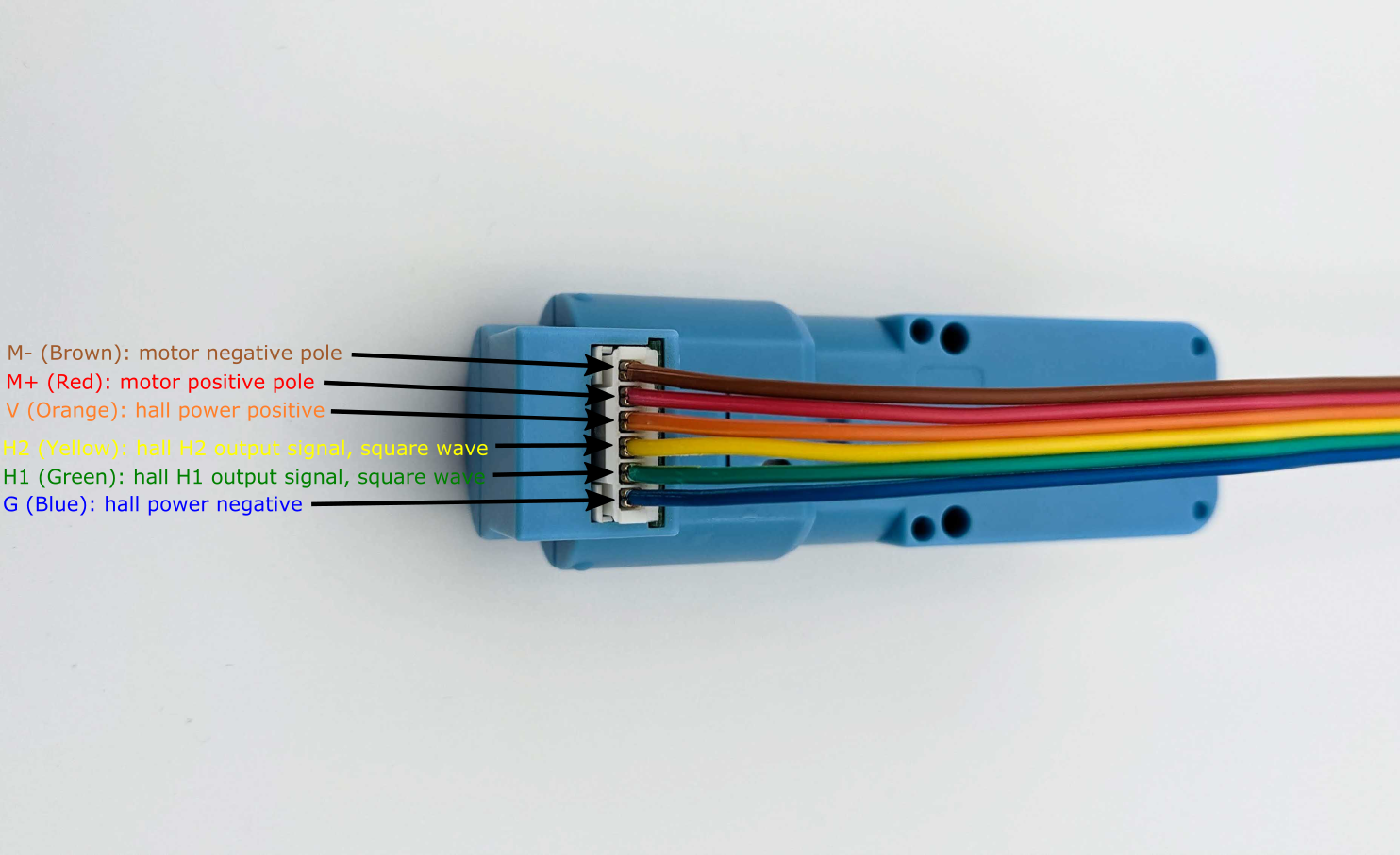
Terminal Pin Layout
The pins on the product are as follows, when looking at the connector on the housing, motor down/connector up, from right to left. The colors correspond to the included cable when plugged in to the connection slot.
- G (Blue): hall power negative
- H1 (Green): hall H1 output signal, square wave
- H2 (Yellow): hall H2 output signal, square wave
- V (Orange): hall power positive
- M+ (Red): motor positive pole
- M- (Brown): motor negative pole
The following image shows the motor from its side with the corresponding pin descriptions:
Wheel Encoder Measurements
This section shows oscilloscope waveform measurements of the quadrature encoder in the DG01D-E motor.
The motor is connected to the Grove I2C Motor Driver that is powerd with 10 VDC.
The motor_example.py applies 50-100% of the 10 VDC which leads to the following output voltages on the motor:
Voltage sweep measurements
- 0:00 Forward Speed 50: 6.5 VDC
- 0:12 Back Speed 50: 6.5 VDC
- 0:23 Forward Speed 60: 6.9 VDC
- 0:34 Back Speed 60: 6.9 VDC
- 0:46 Forward Speed 70: 7.2 VDC
- 0:56 Back Speed 70: 7.2 VDC
- 1:07 Forward 80: 7.3 VDC
- 1:18 Back 80: 7.3 VDC
- 1:29 Forward 90: 7.6 VDC
- 1:41 Back 90: 7.6 VDC
- 1:52 Forward 100: 7.9 VDC
- 2:02 Back 100: 7.9 VDC
At the bottom of the pico scope window the cycle time, duty cycle, high and low pulse width measurements are shown for both encoder signals. Oscilloscope is the PicoScope 3000 Series with 2 Channels. To download and install Pico Scope software on Linux refer to the documentation.
Summary of installation instructions
- Add repository to the updater
sudo bash -c 'echo "deb https://labs.picotech.com/debian/ picoscope main" >/etc/apt/sources.list.d/picoscope.list' - Import public key
wget -O - https://labs.picotech.com/debian/dists/picoscope/Release.gpg.key | sudo apt-key add - - Update package manager cache
sudo apt-get update - Install PicoScope
sudo apt-get install picoscope
Comments