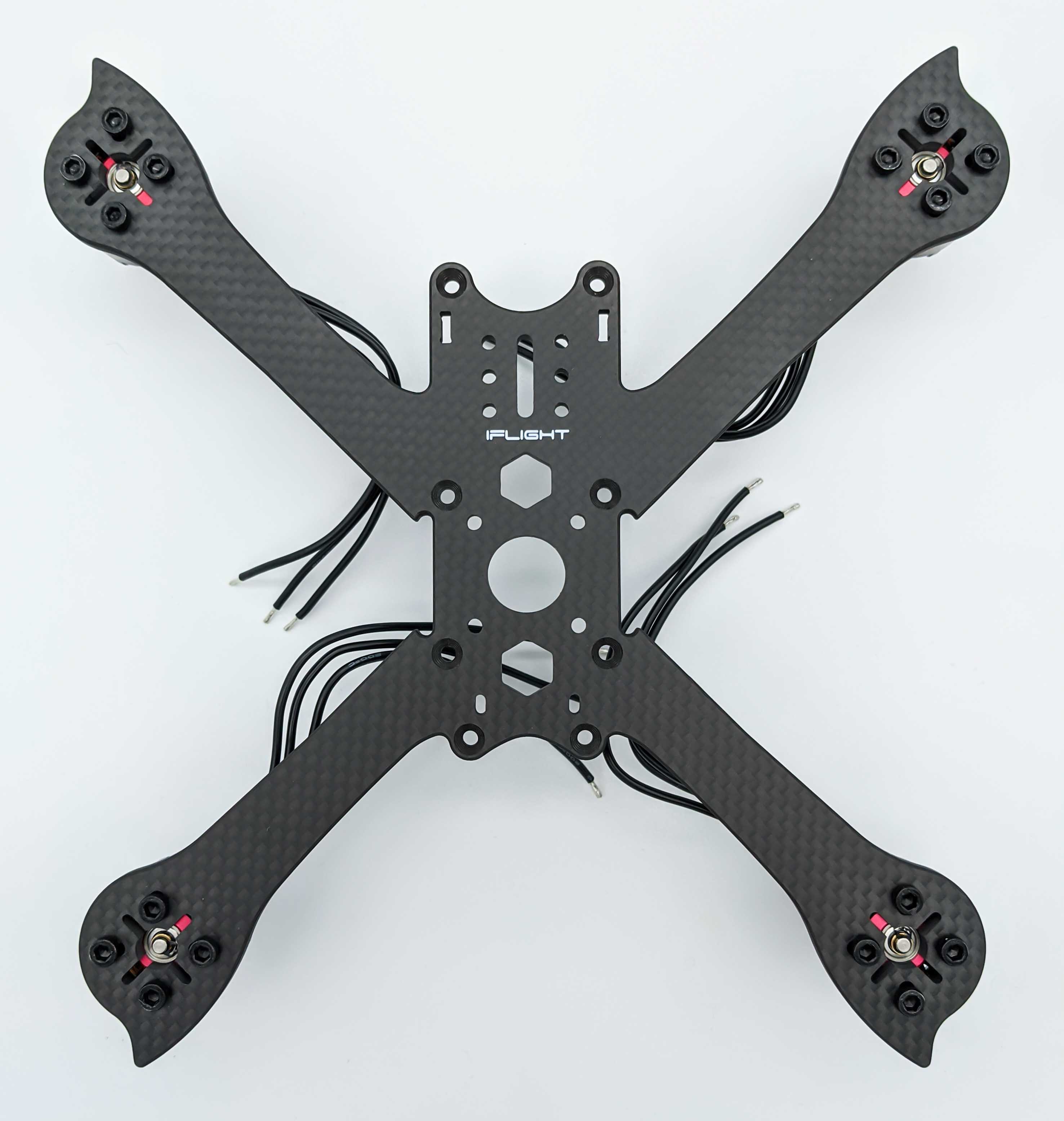
After selecting all components of a race quad it is time to assemble everything together. First, we have to decide where each part will be located in the quad. Therefore, we assembe the frame and mount each component to its final location inside the frame.
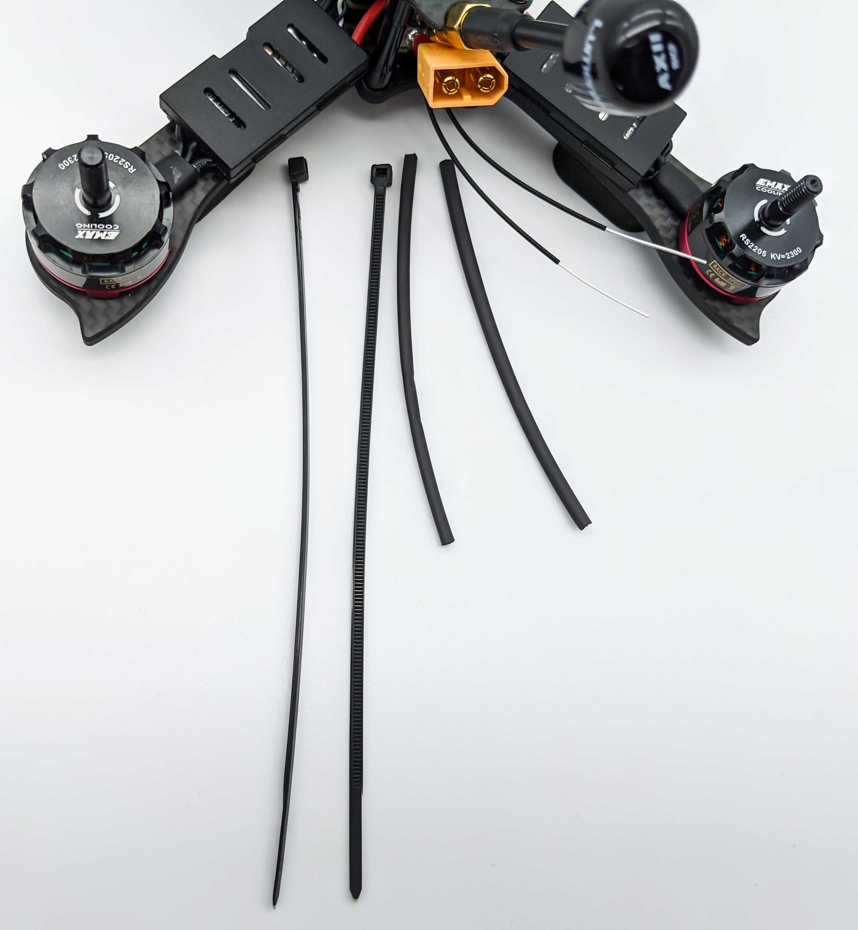
Several components need to be prepared for the assembly, because they need for example some soldering or heat shrinks applied.
Motor Mounting
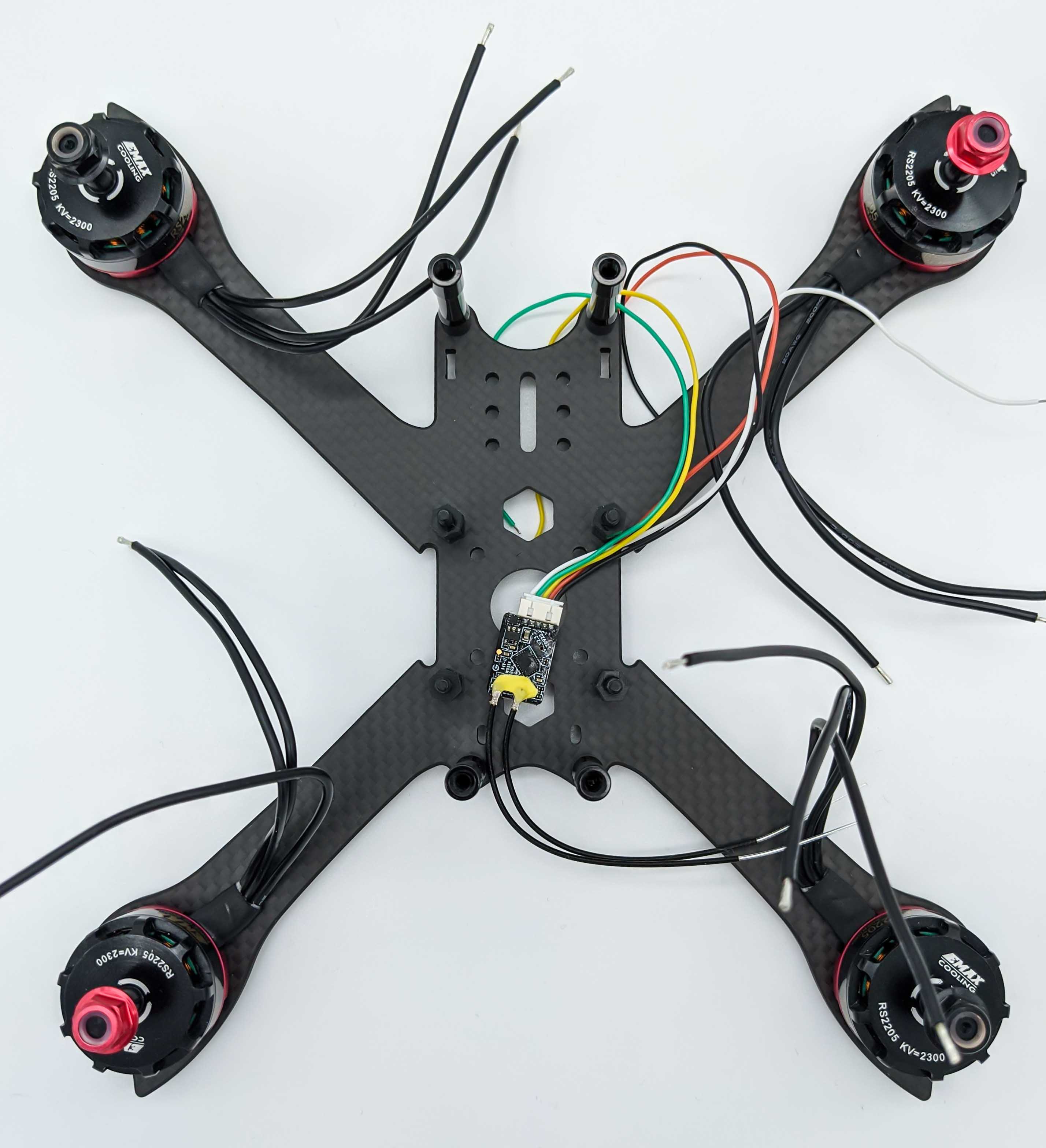
First we mount the four motors to the base plate of the frame. Thereby we have to take care of the direction the motor rotates (CW and CCW) and wheather the motor has a CW or CCW shaft thread. Because we will use BetaFlight to configure the Flight Controller we use the default motor configuration of this firmware.
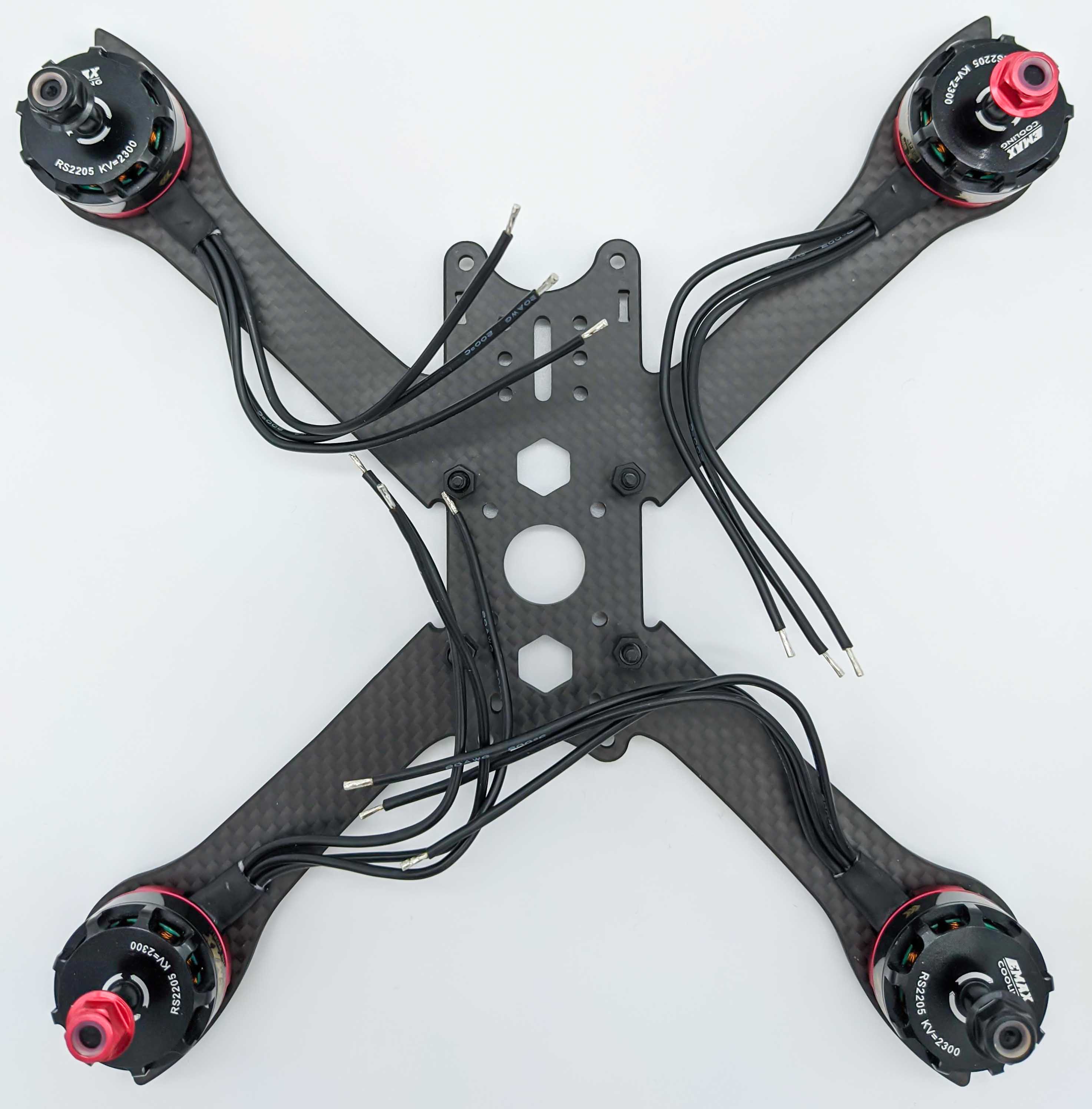

After we’ve figured out the correct location of the motors on each arm, we fix them with the provided screws to the frame:
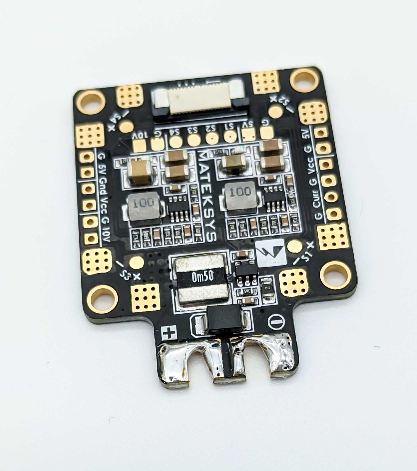
Power Distribution Board Assembly
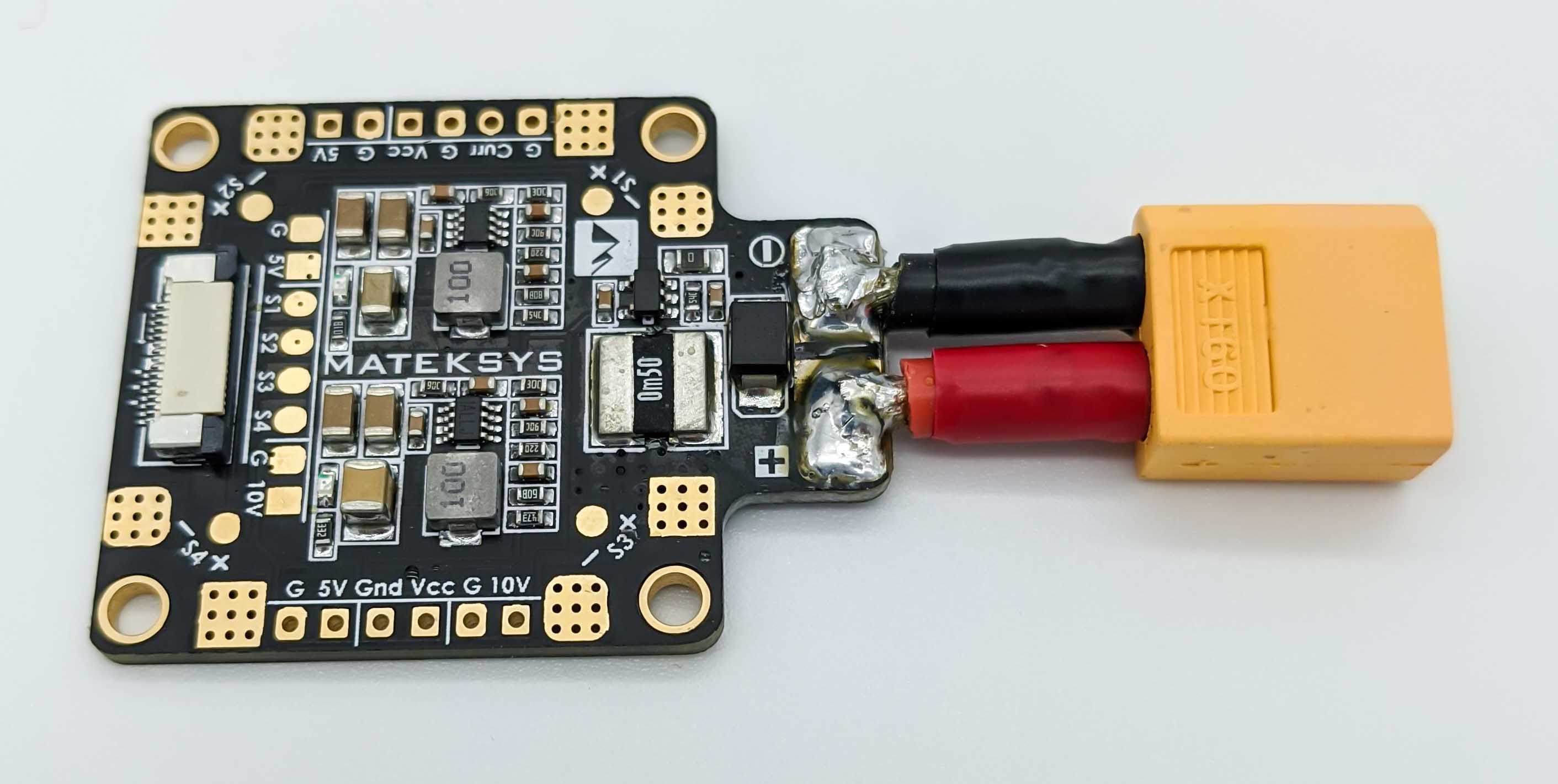
Let’s begin preparing the Power Distribuiton Board. The PDB is powerd with the battery pack via an XT60 plug.
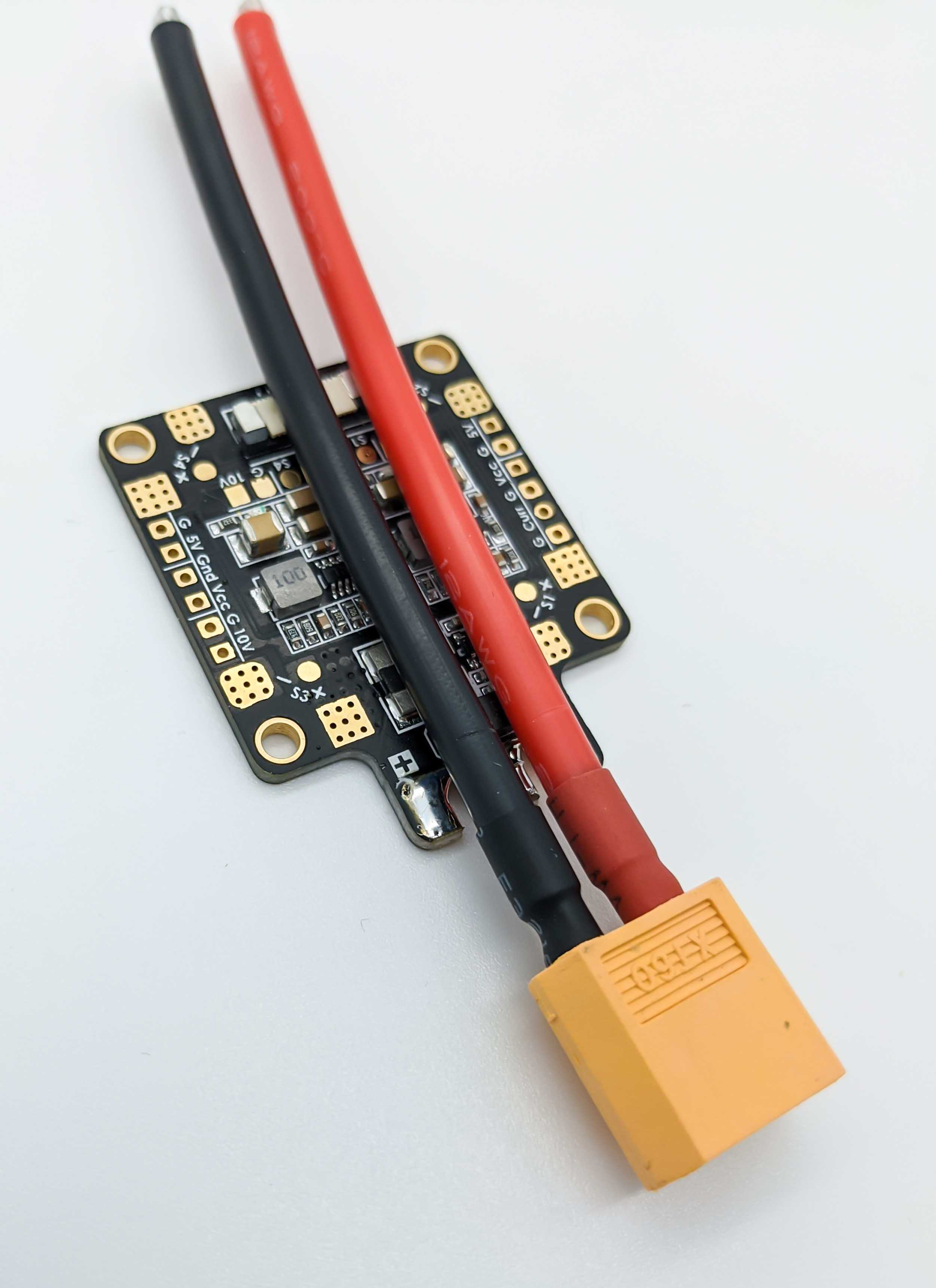
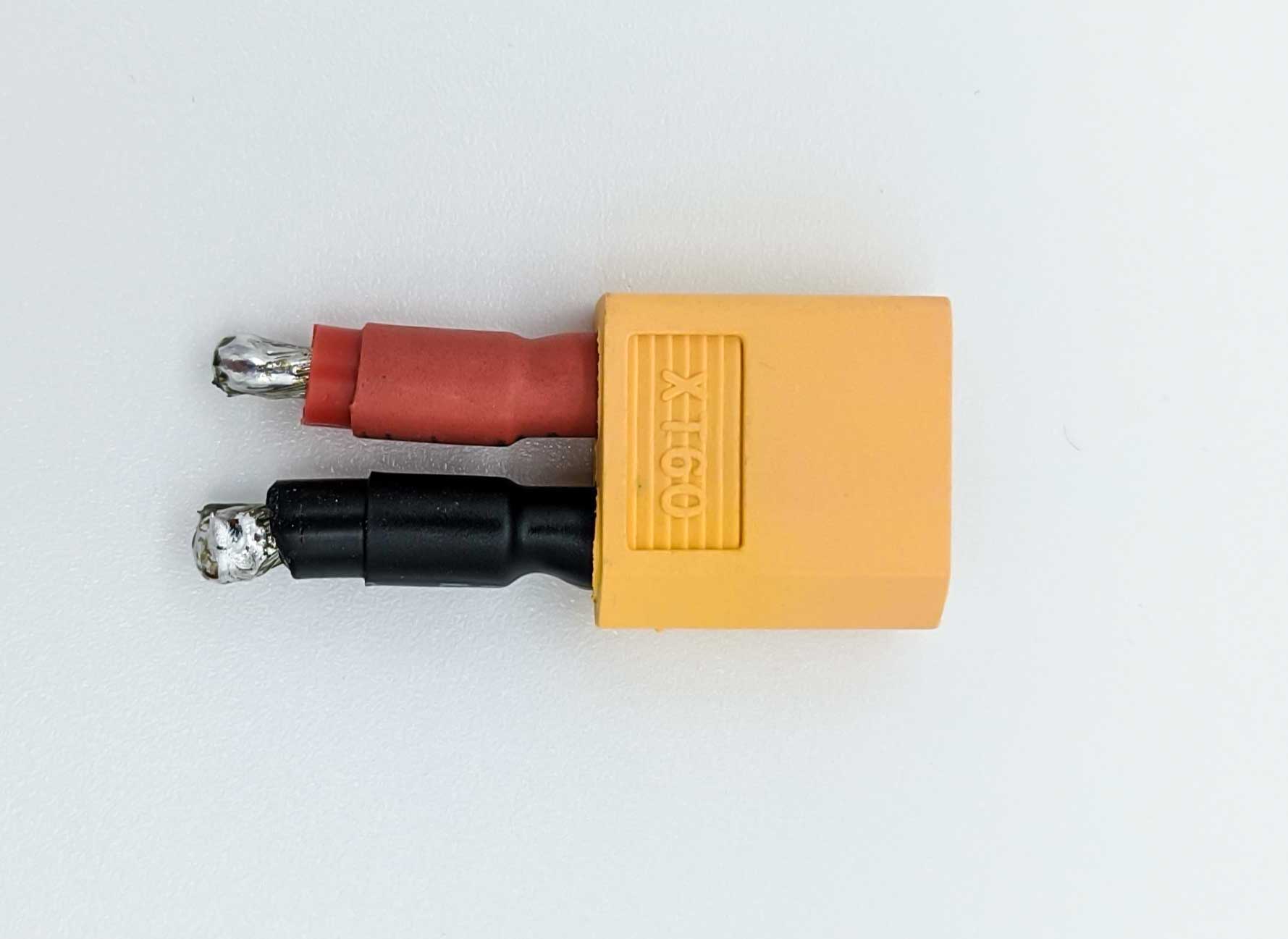
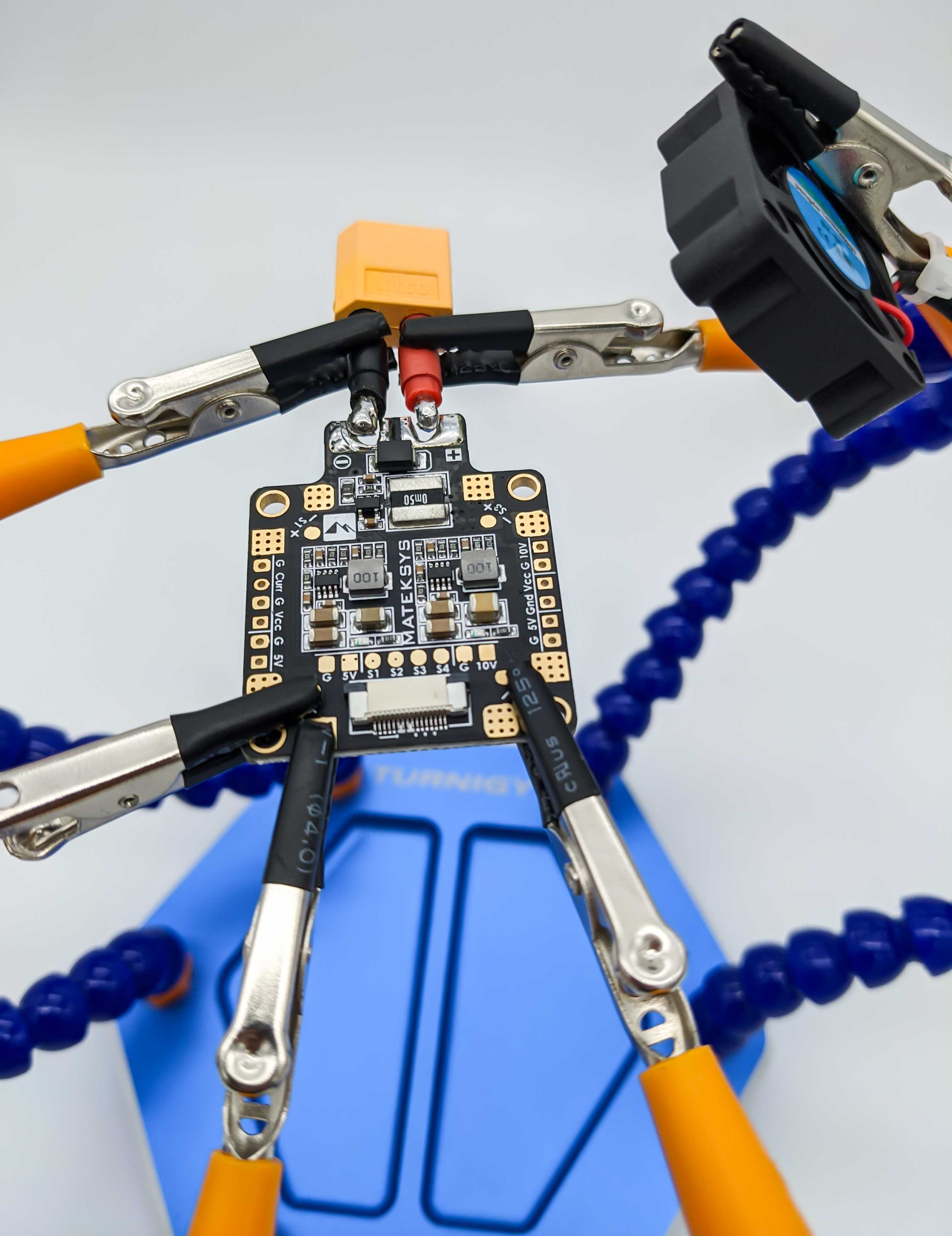
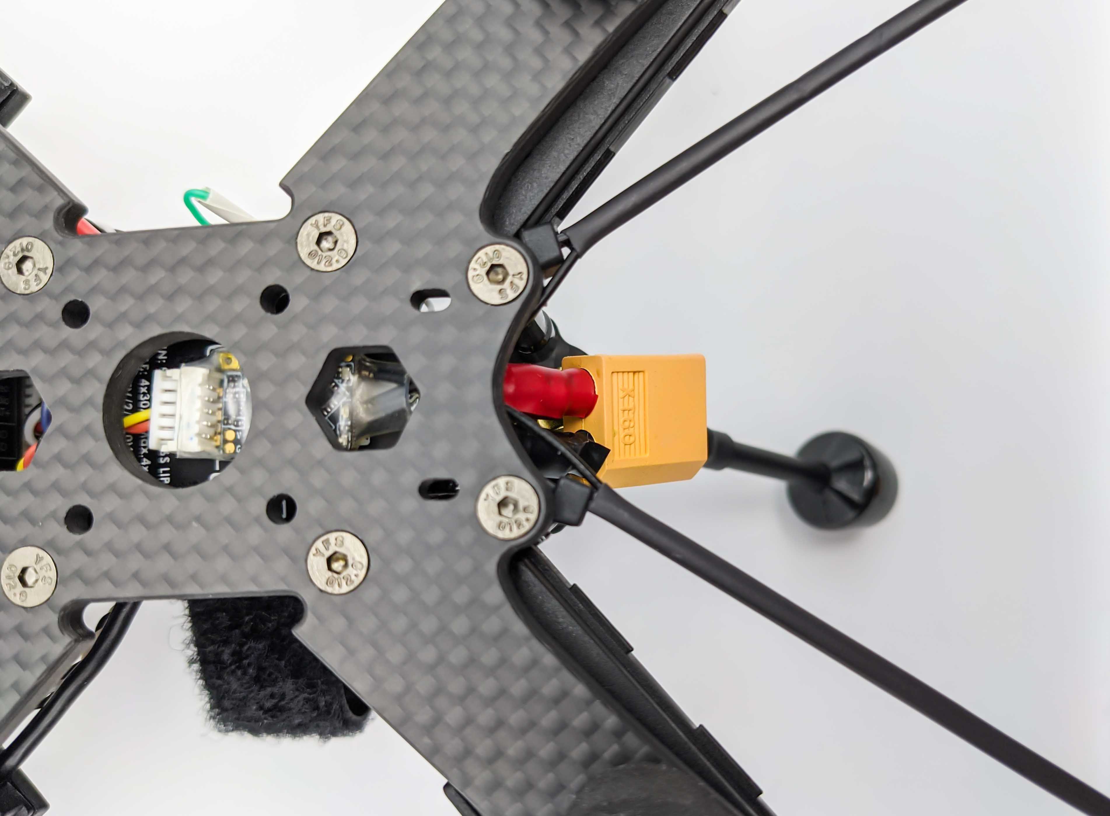
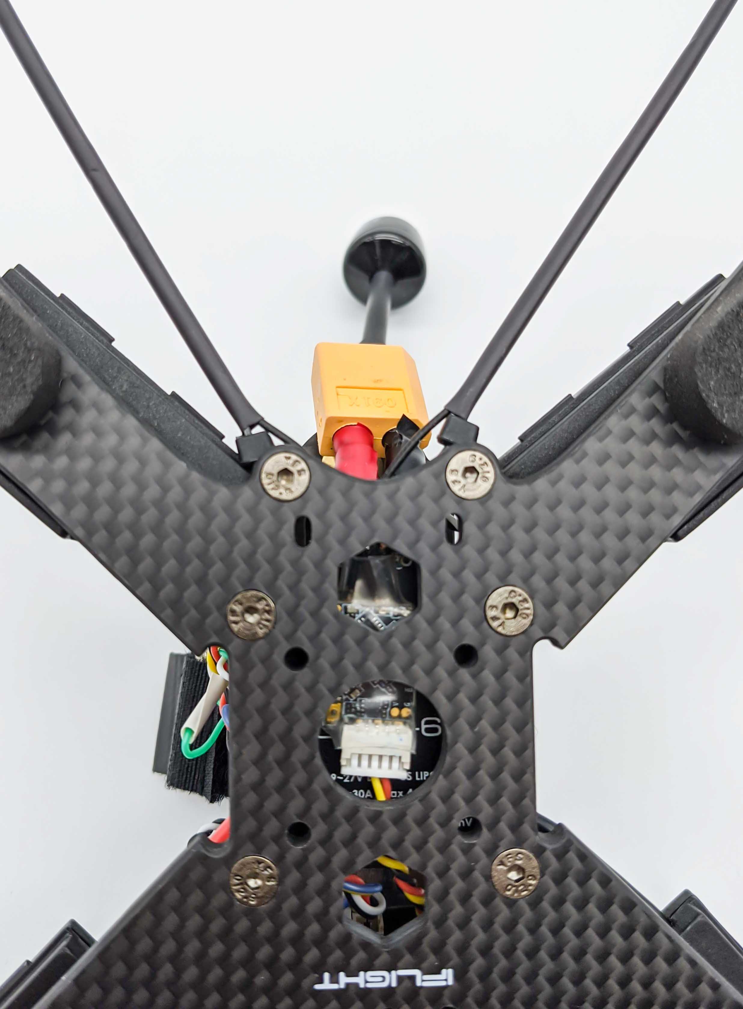
Solder the XT60 plug to the PDB and keep the spinning propellers in mind to solder the XT60 in an appropriate orientation to avoid collisions between the parts.
Test PDB Power Connection
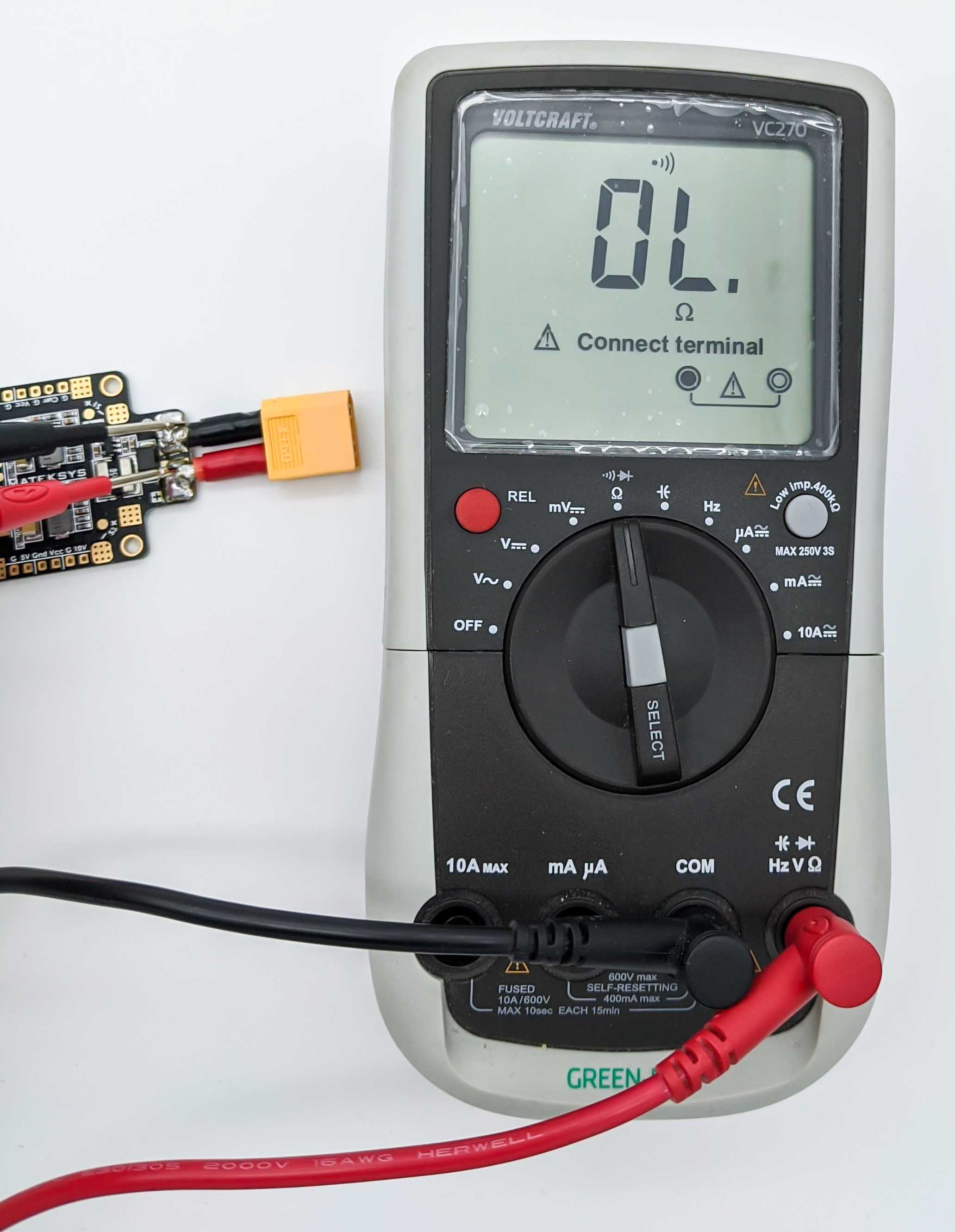
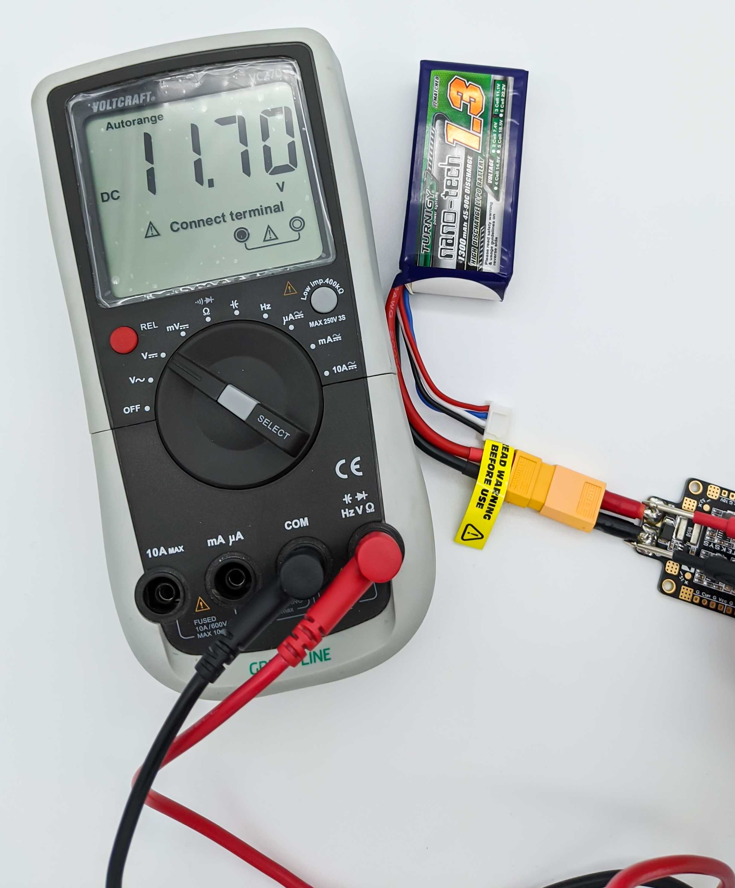
After soldering the battery connector, we test the connection using a multimeter. First, perform a continuity test between plus and minus connector to verify that no short connection was produced while soldering. To verify no short connection exists, the multimeter should NOT beep, otherwise the two leads are connected. A short would result in a high current flow from the battery plus to minus with dangerous consequences.
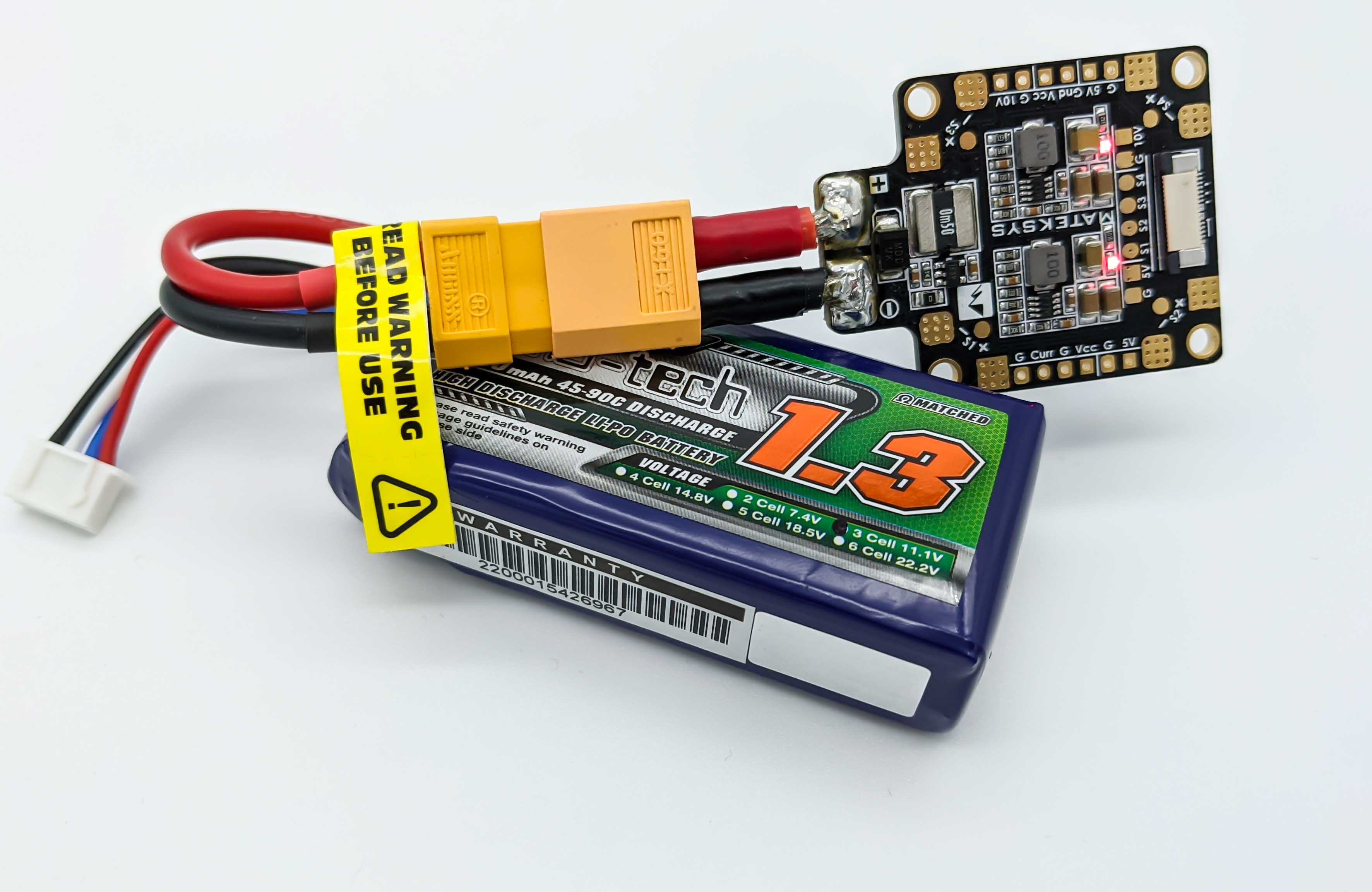
After verifying that no short exists, we can perform a (small) smoke test to test the connection on the PDB so far. Therefore we connect a battery which should hopefully cause no smoke. If that is the case, we can check the voltage across the pads. Be careful though, to not produce a short with the mulimeter probes.
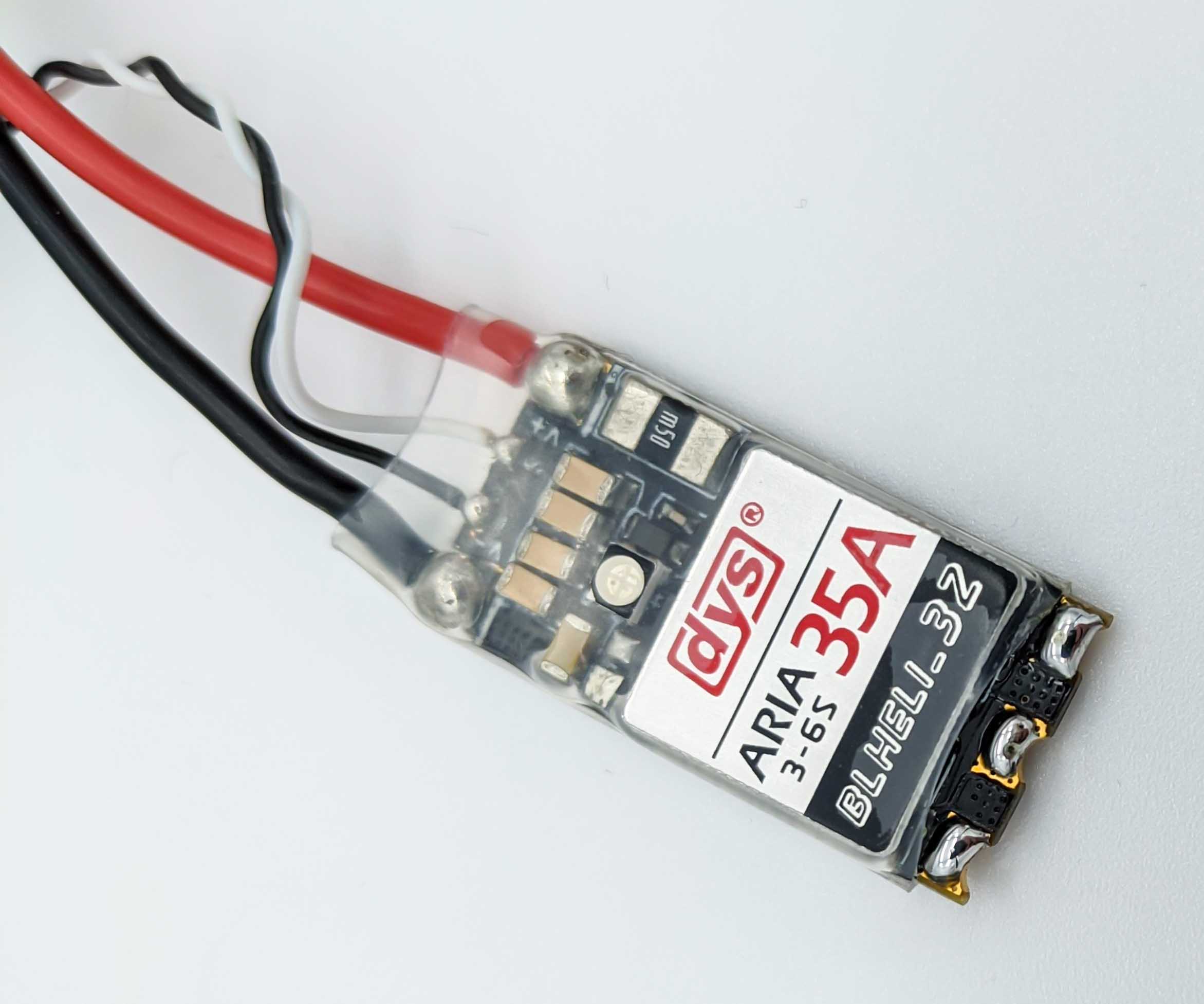
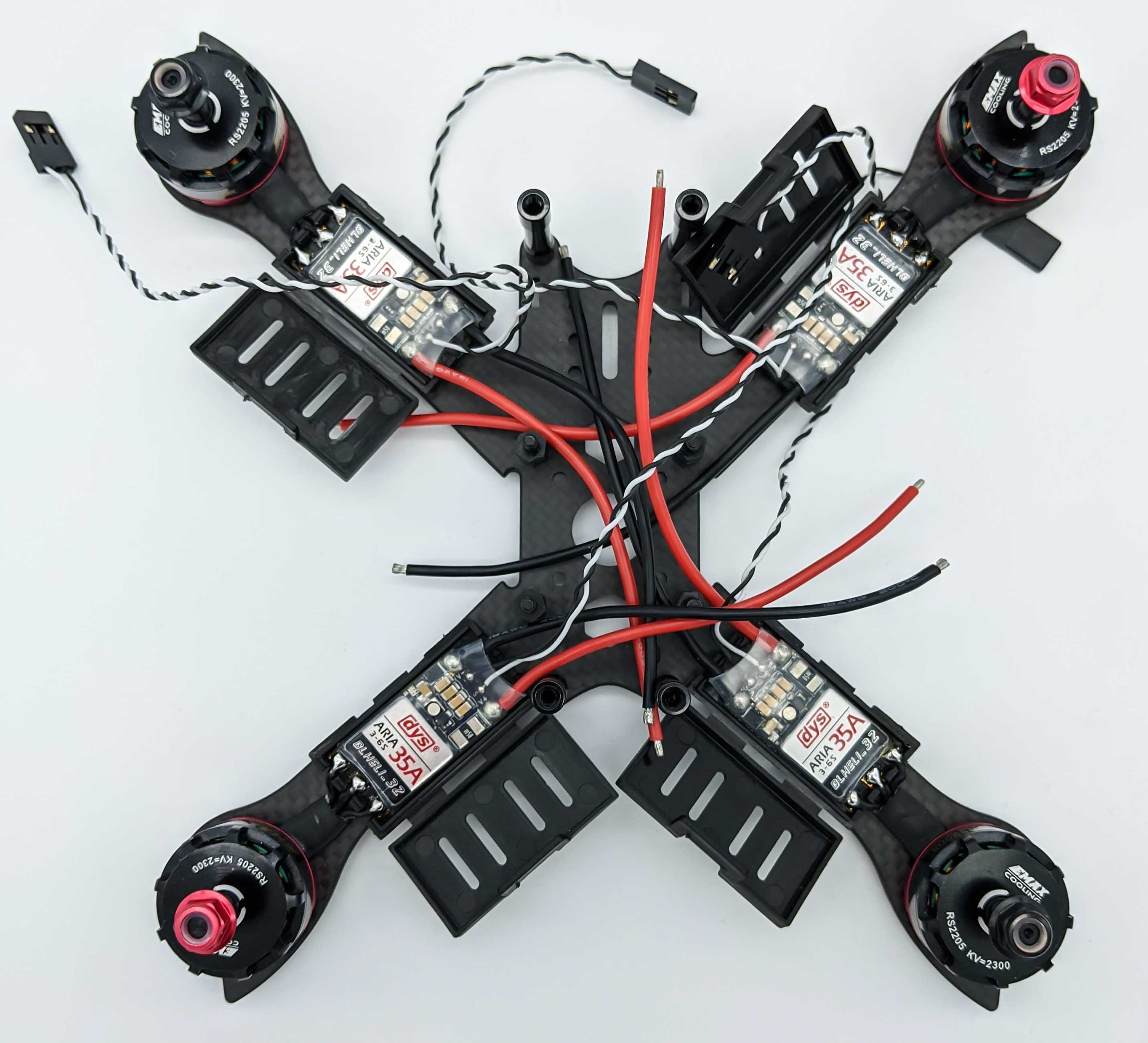
Install ESCs
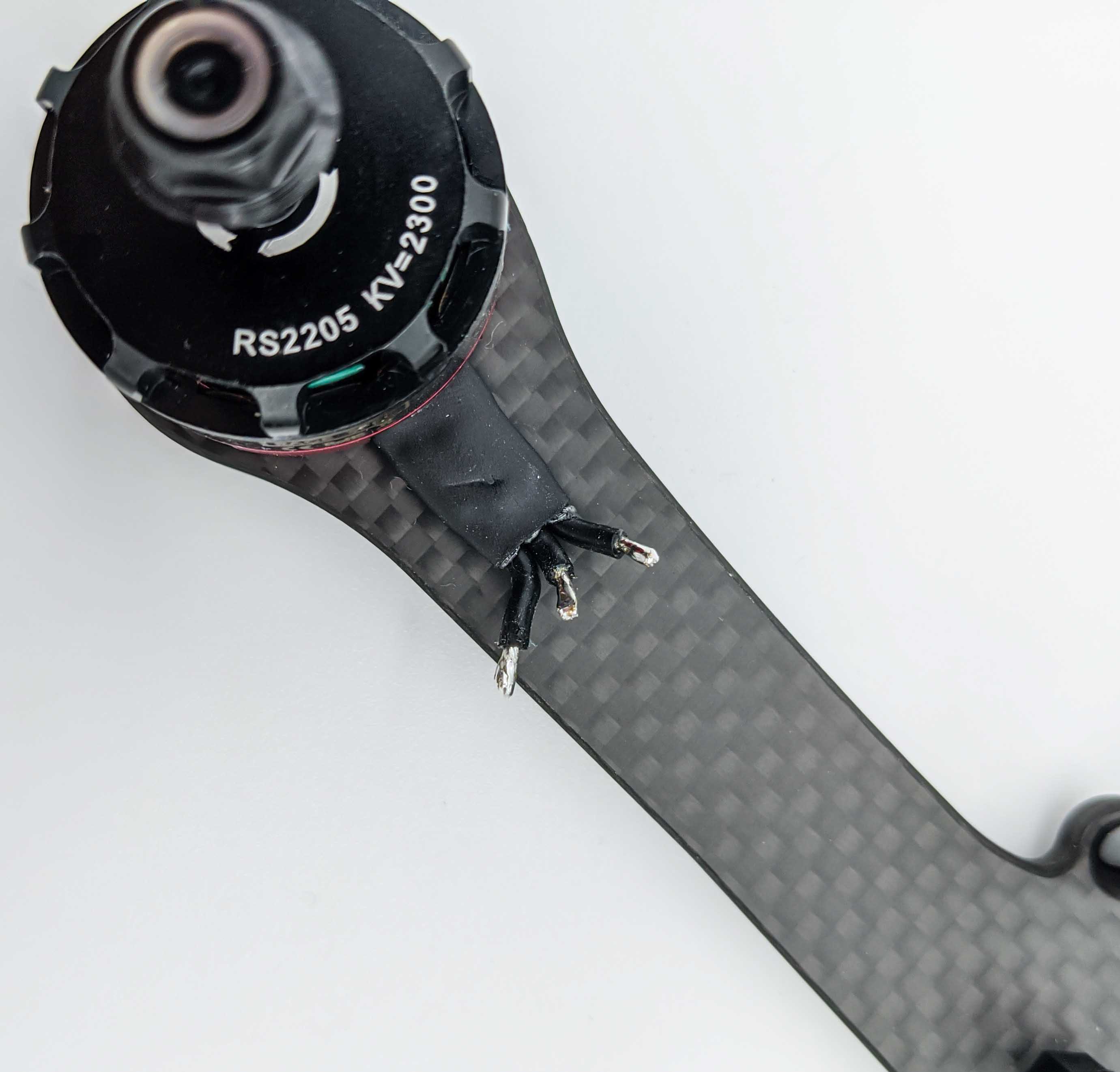
To install the [ESC]s we place them on the individual copter arms and measure the three motor phase wires. The image below shows that the wires will be soldered to solder pads that are closest to each motor phase wire.
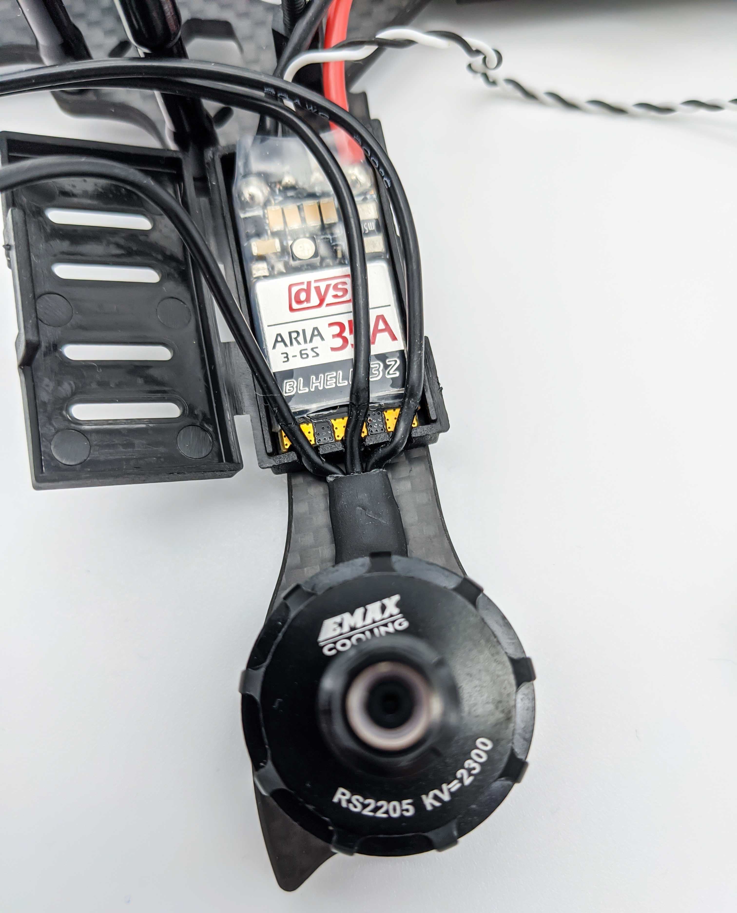
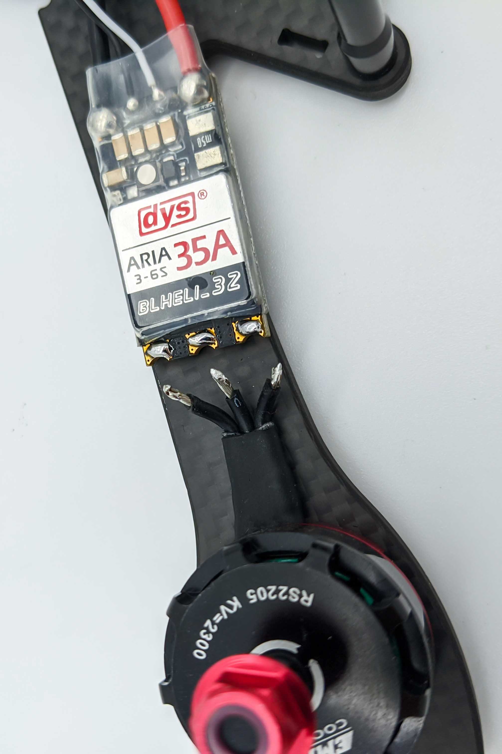
After, the ESC is placed accordingly, we strip the isolation of the three motor phase wires:
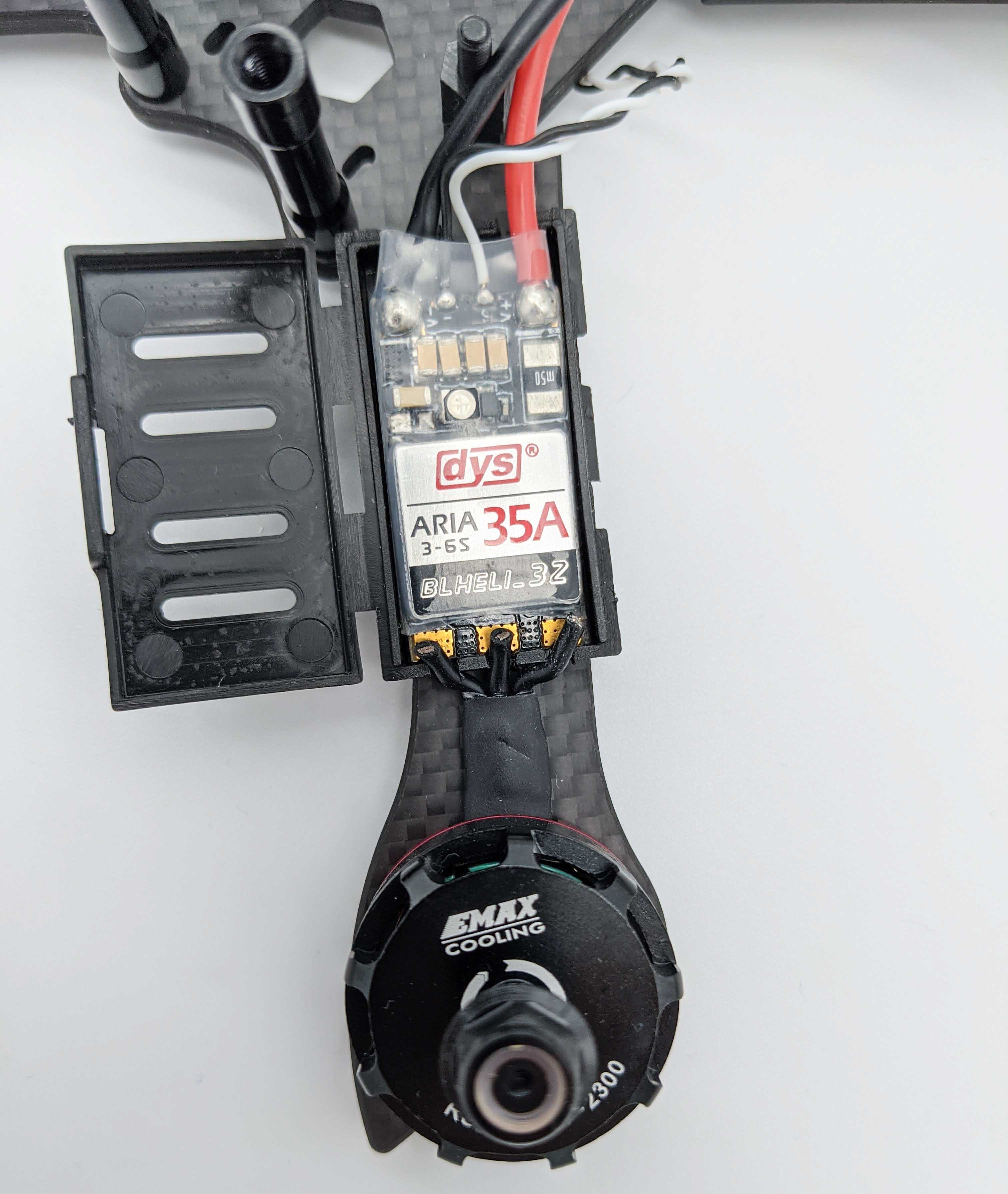
Now we can tin the wires and the ESC solder pads.
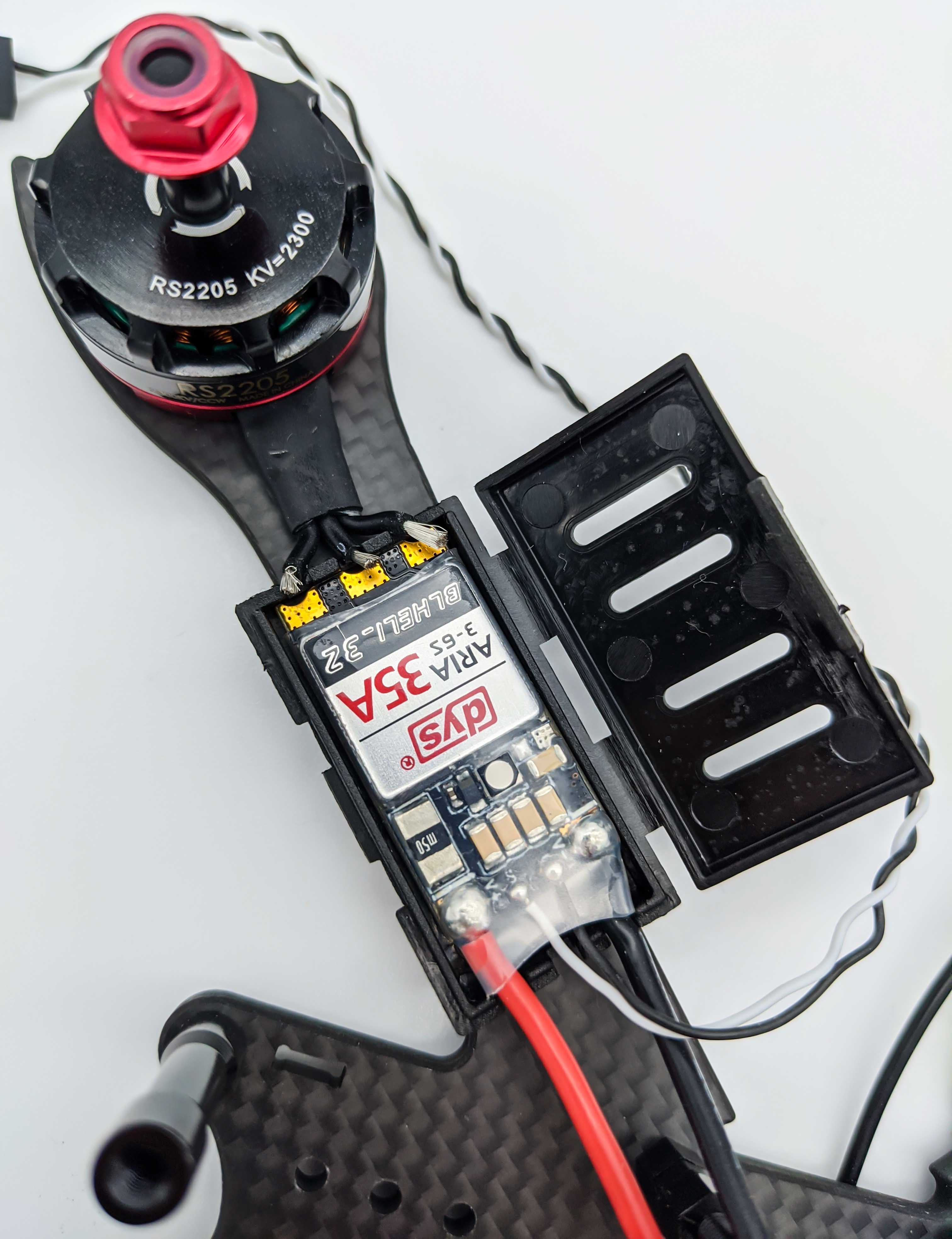
Solder the tinned motor phase wires to the ESC solder pads:
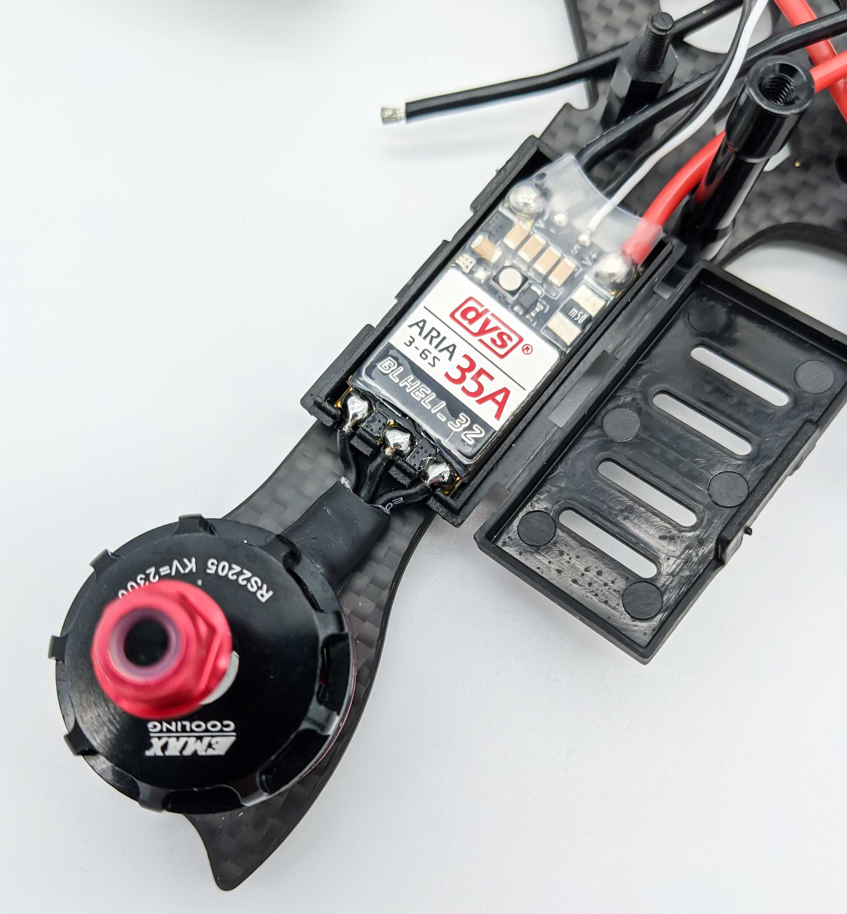
To supply the ESC with power we measure the plus and minus wires of the ESCs to fit to the dedicated ESC pads on the Power Distribution Board:
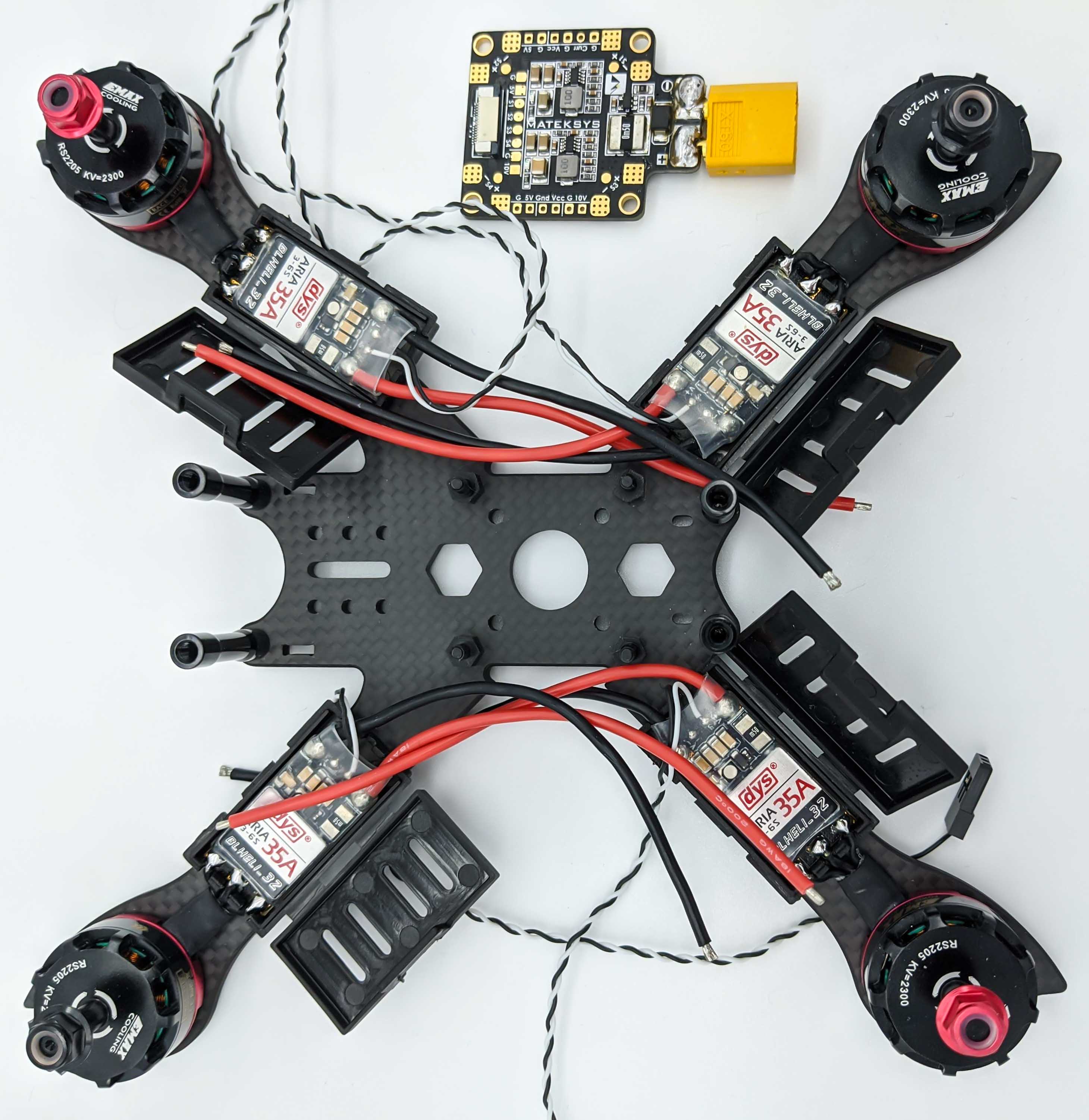
After we’ve cut the ESC power wires to the correct length we are ready to prepare the other parts, such as the FPV system.
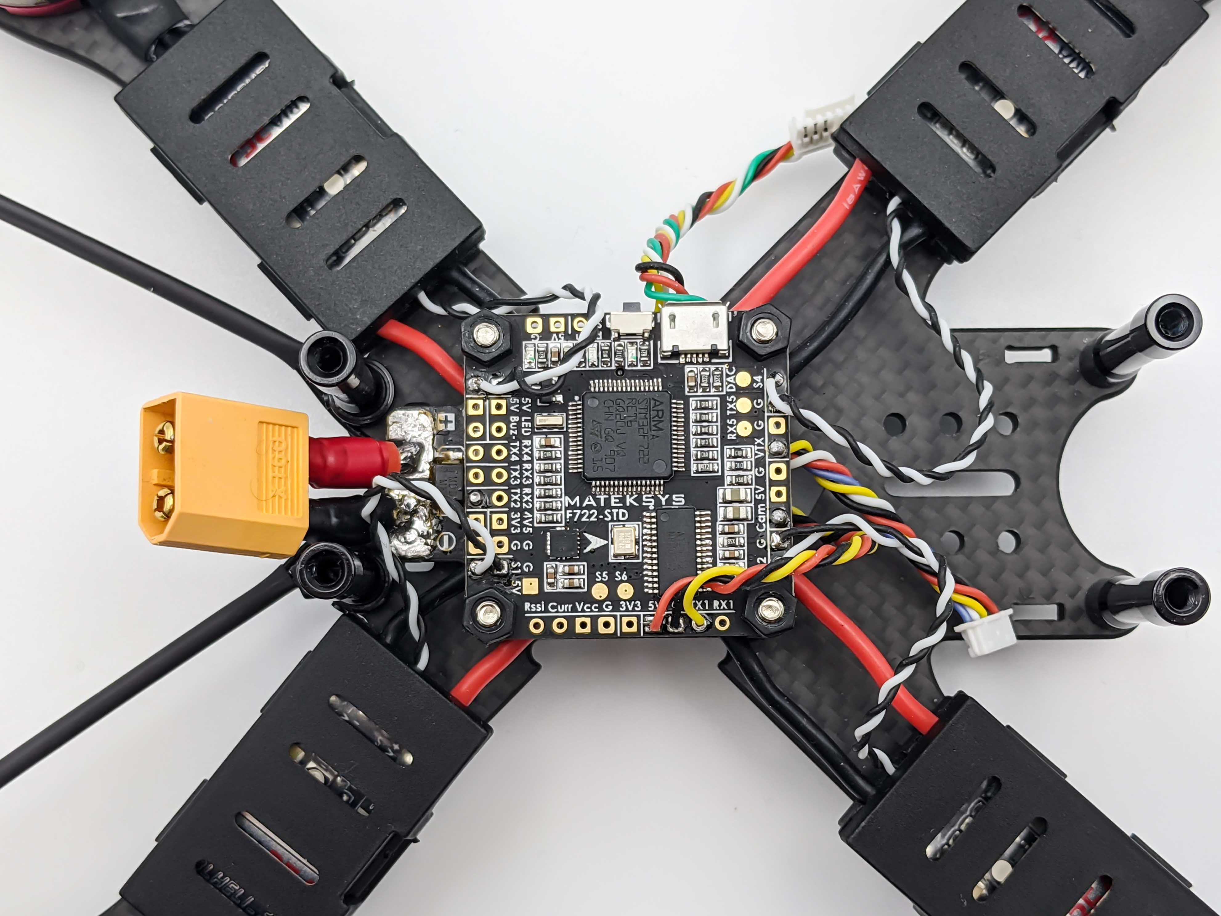
Prepare the Flight Controller
Tin the pins of the Flight Controller (FC) that will be used to connect components such as the control wires of the ESCs and the FPV System. The required pins will be shown in the following sections, where the individual compoenents are prepared and connected to the FC.
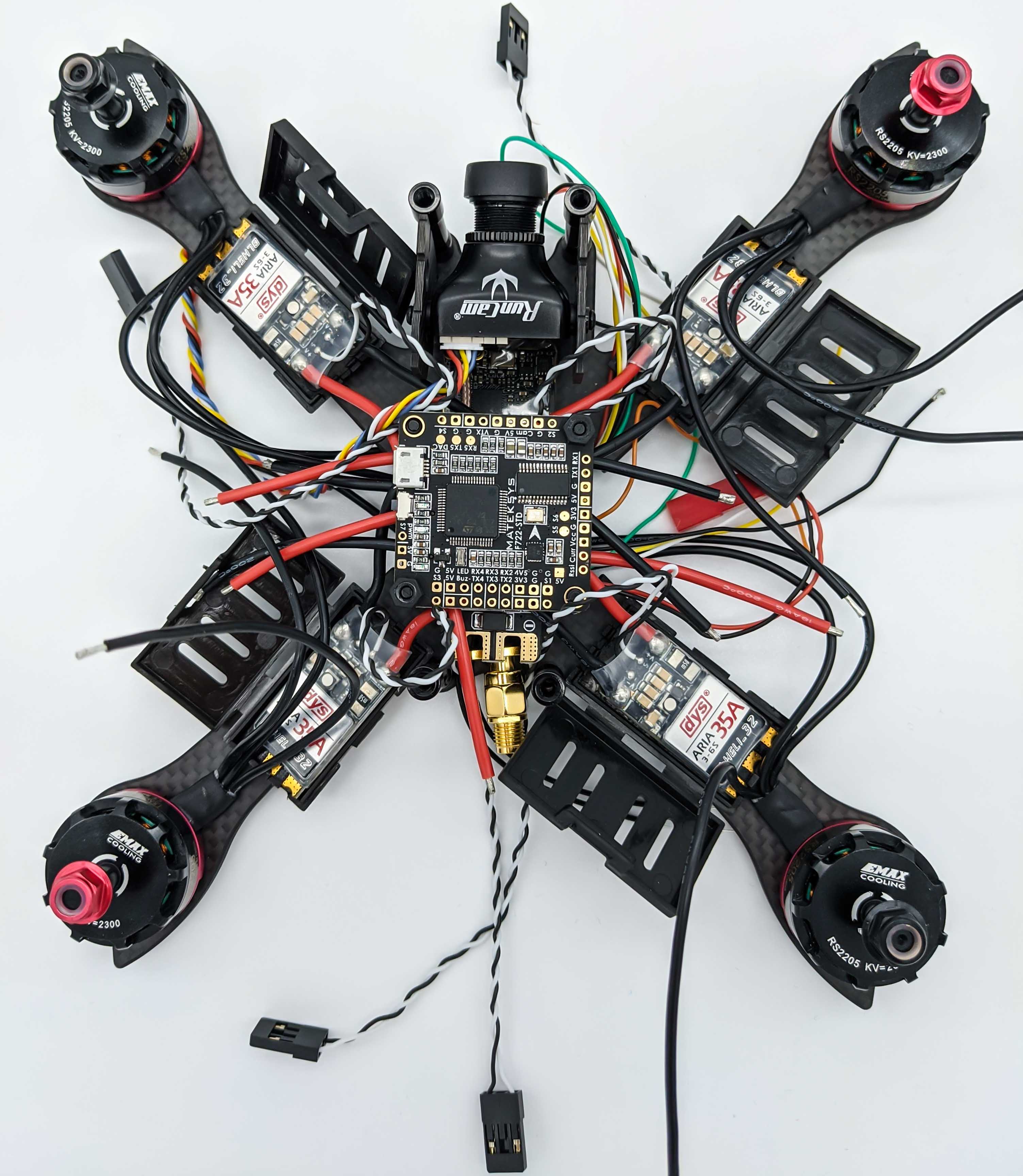
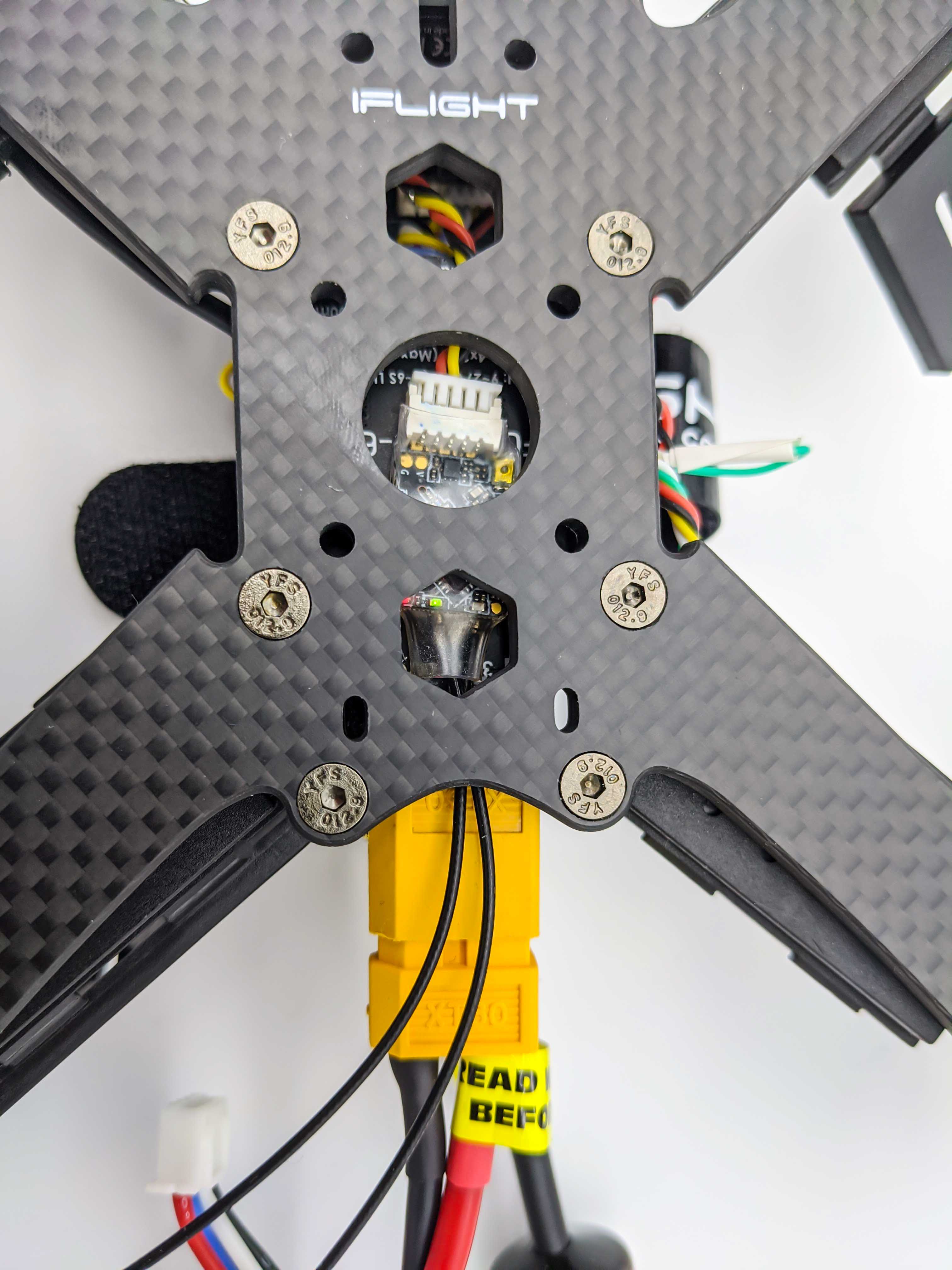
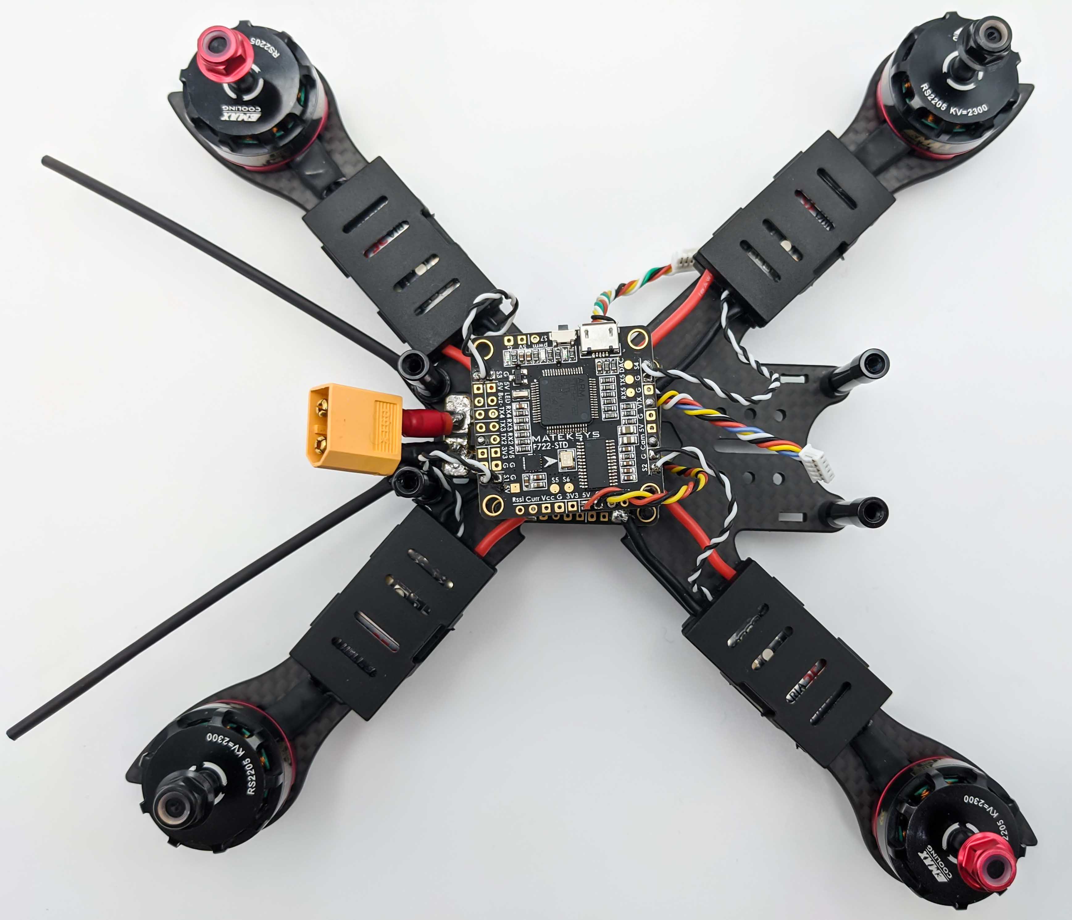
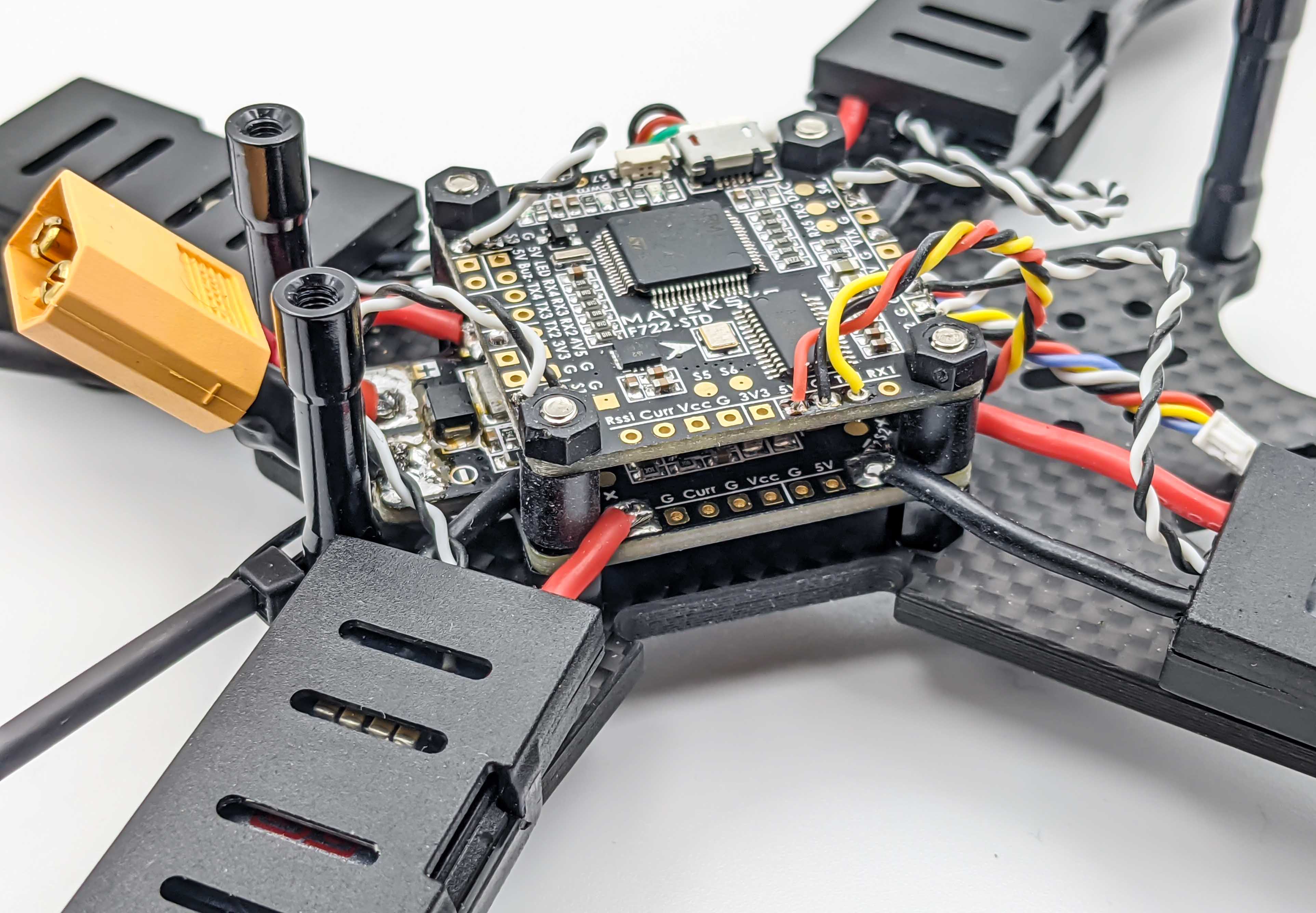
The FC will be placed above the PDB where rubber standoffs help to reduce unwanted noisy measurements in the sensors of the FC (gyroscope and accelerometer, see IMU).
FPV System
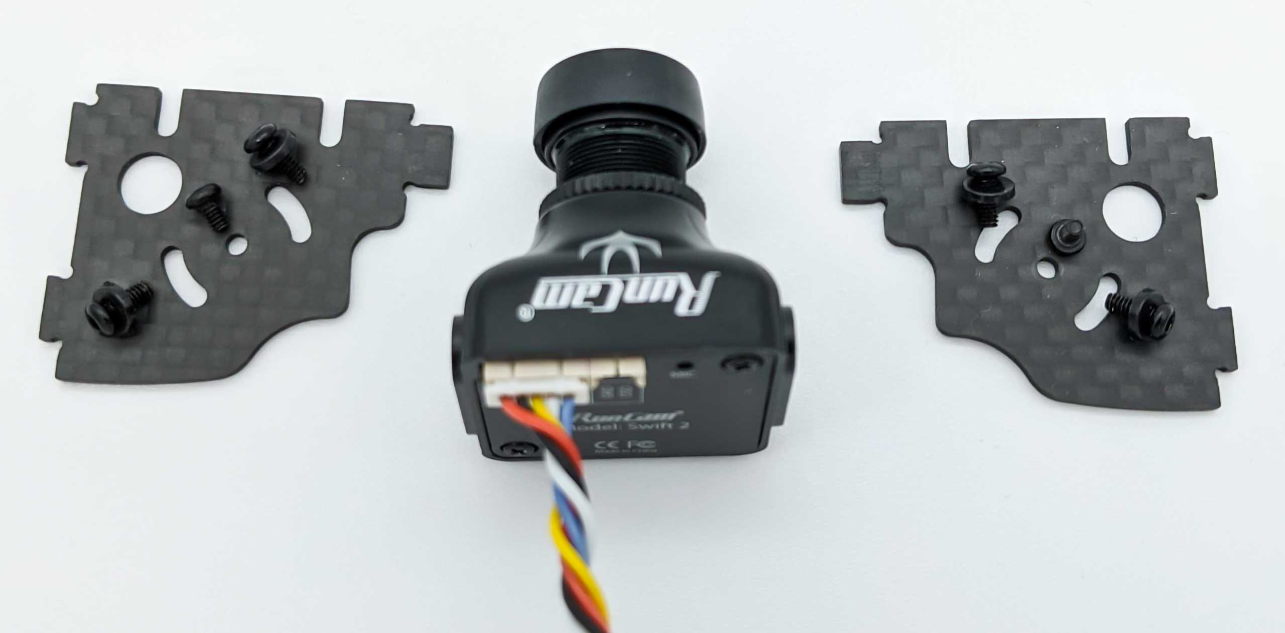
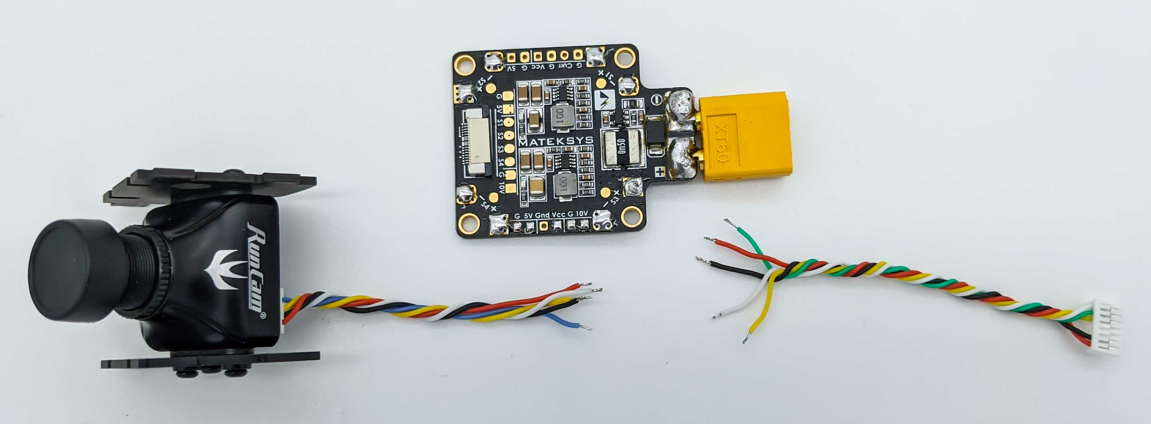
Camera Setup
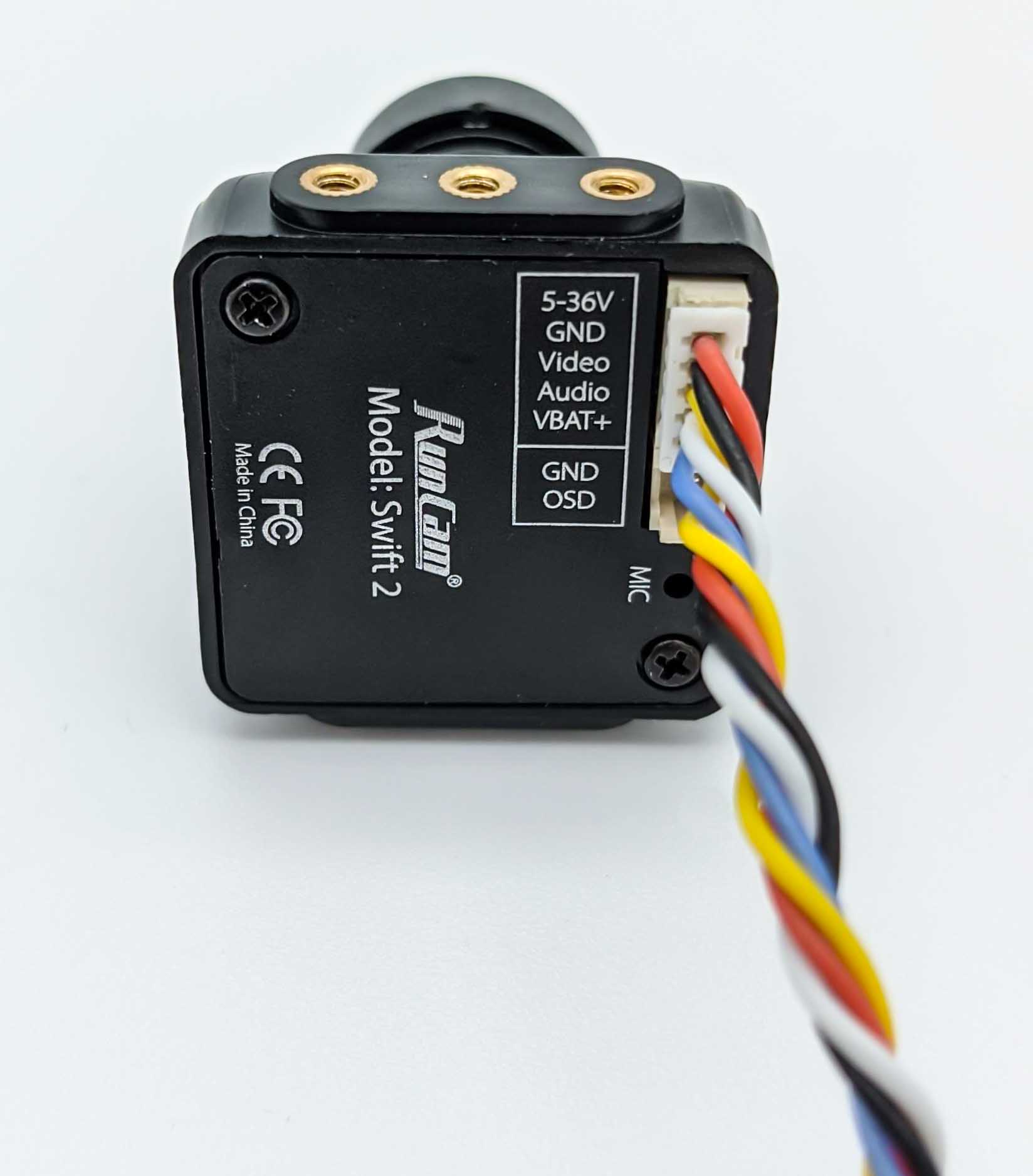
The RunCam Swift 2 camera will be mounted to the parts provided by the iFlight frame.
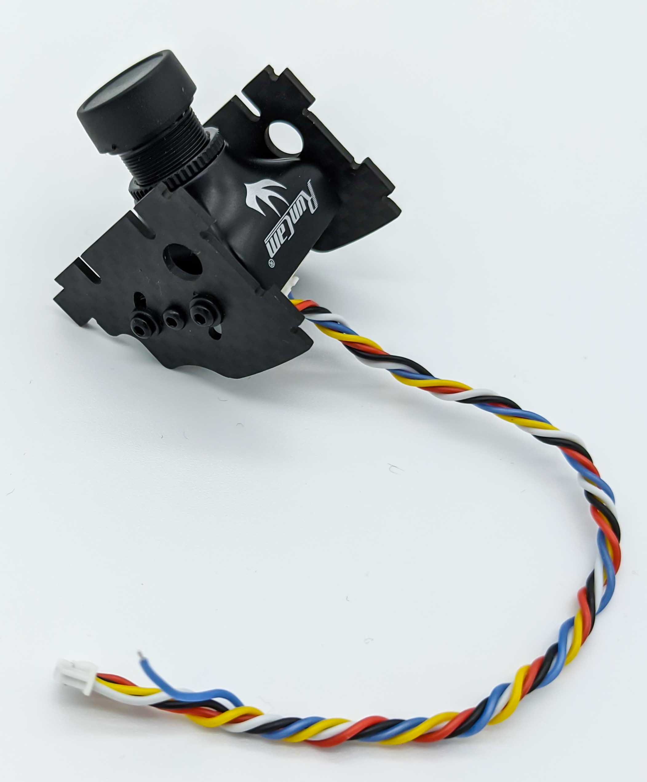
The provided camera connector connects the camera port to power and the video output signal to the VTX.
To connect the camera to the VTX it will be prepared in the next section.
VTX Preparation
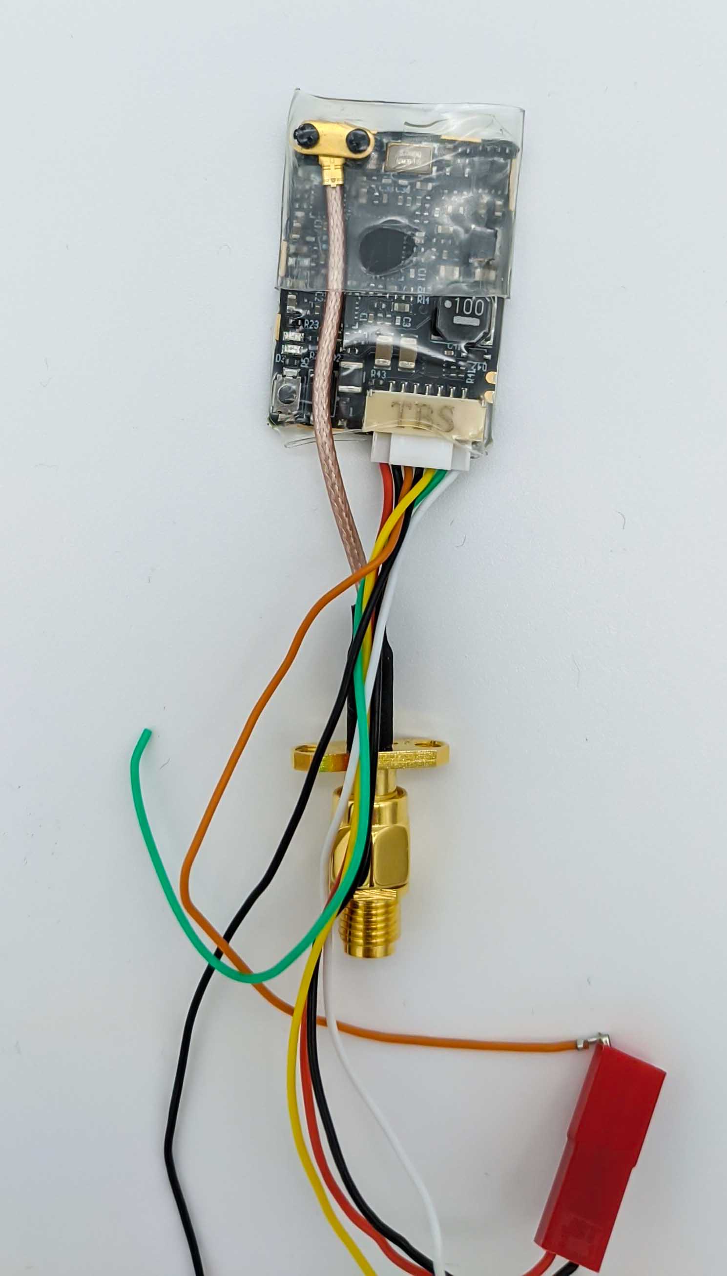
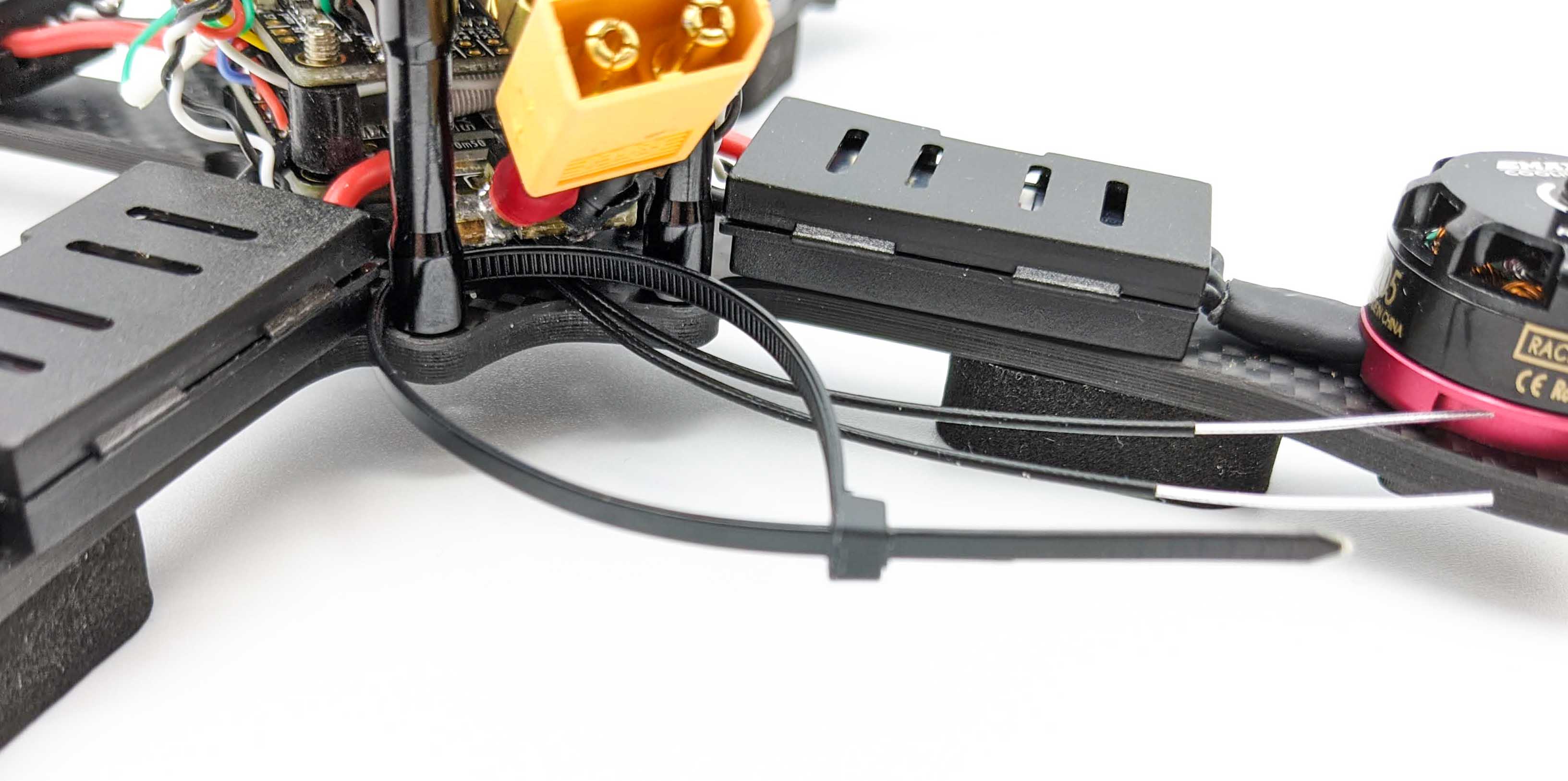
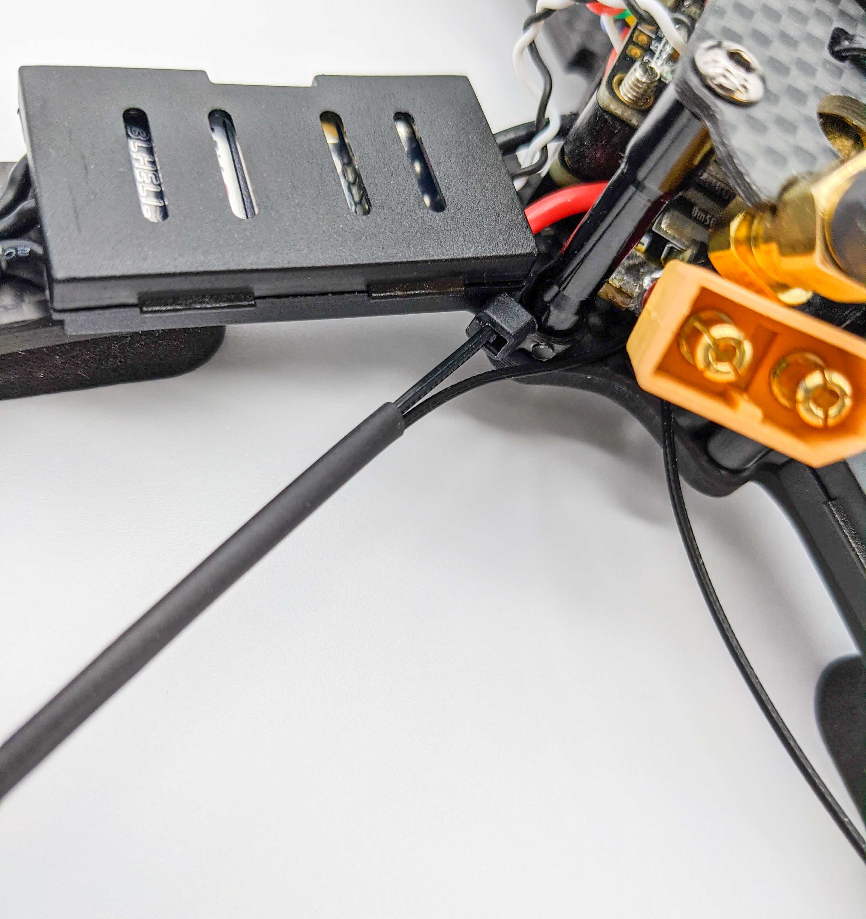
Depending on the final placement of the VTX in the copter the antenna needs to be adjusted as shown in the image below. Also make sure that the program button on the VTX is reachable when mounted. This way it is possible to switch bands and other settings such as the (allowed) signal strength later on.
When you found the right antenna pig tail position, apply some shrink tubing to the VTX:
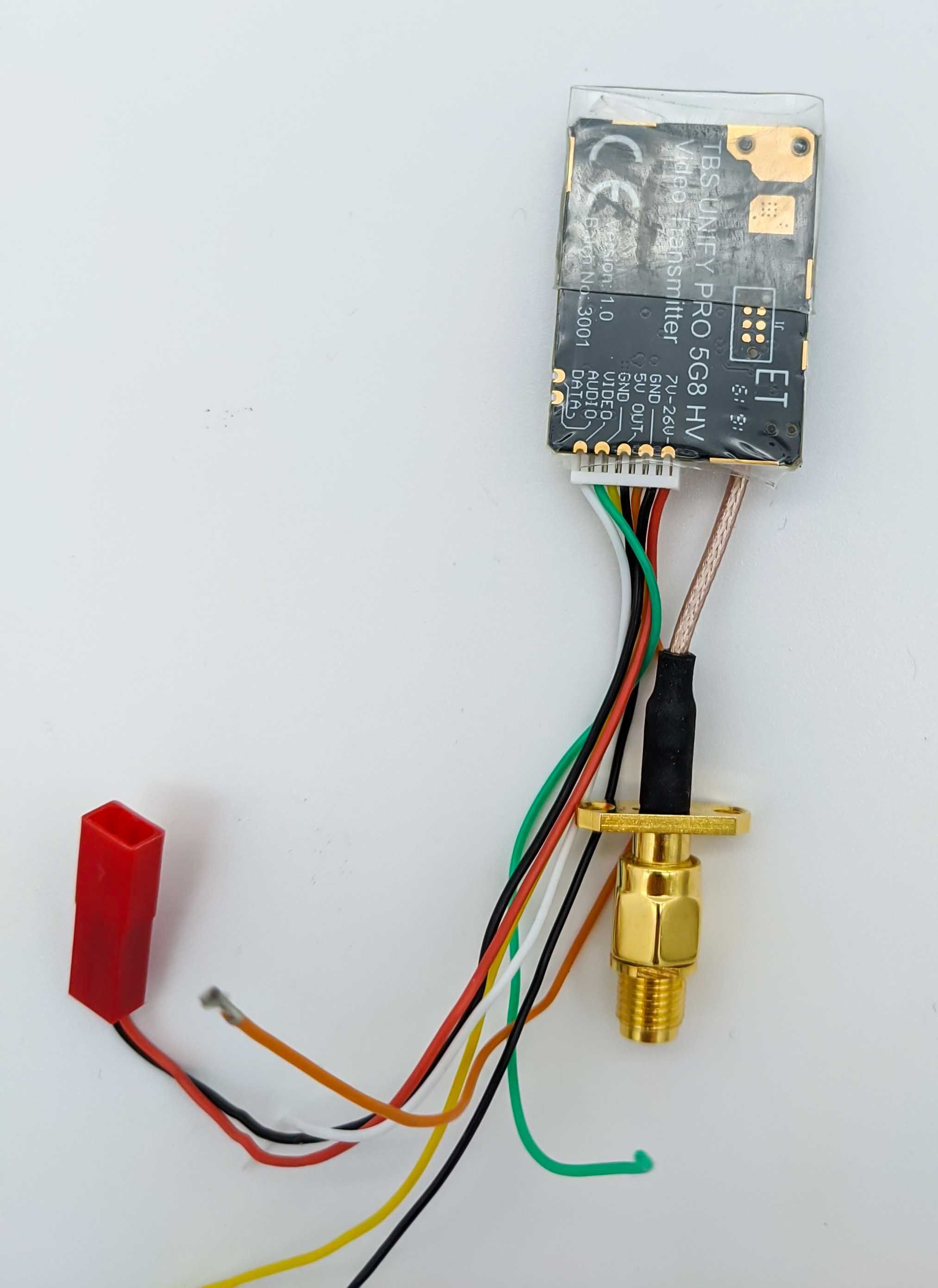
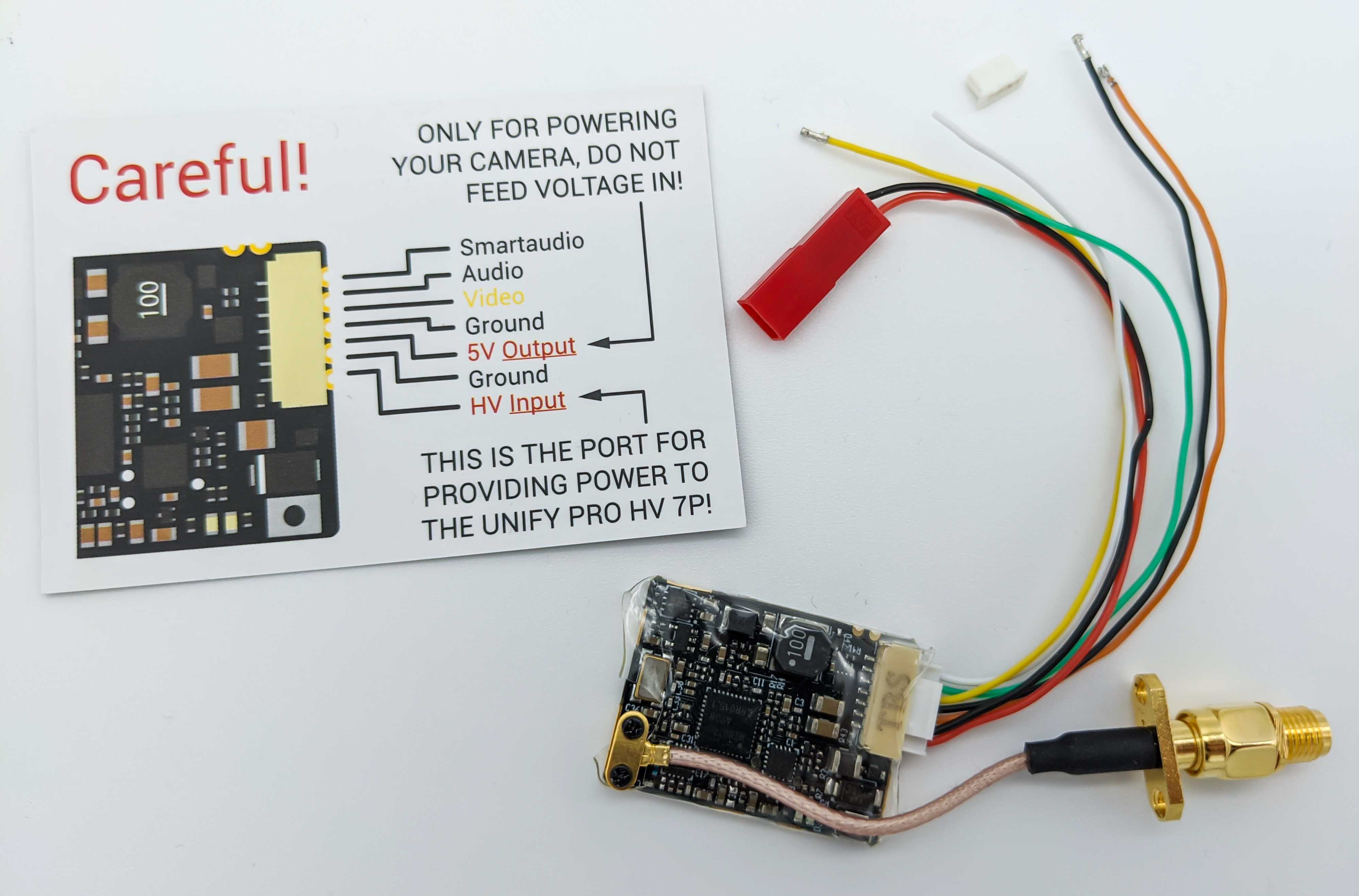
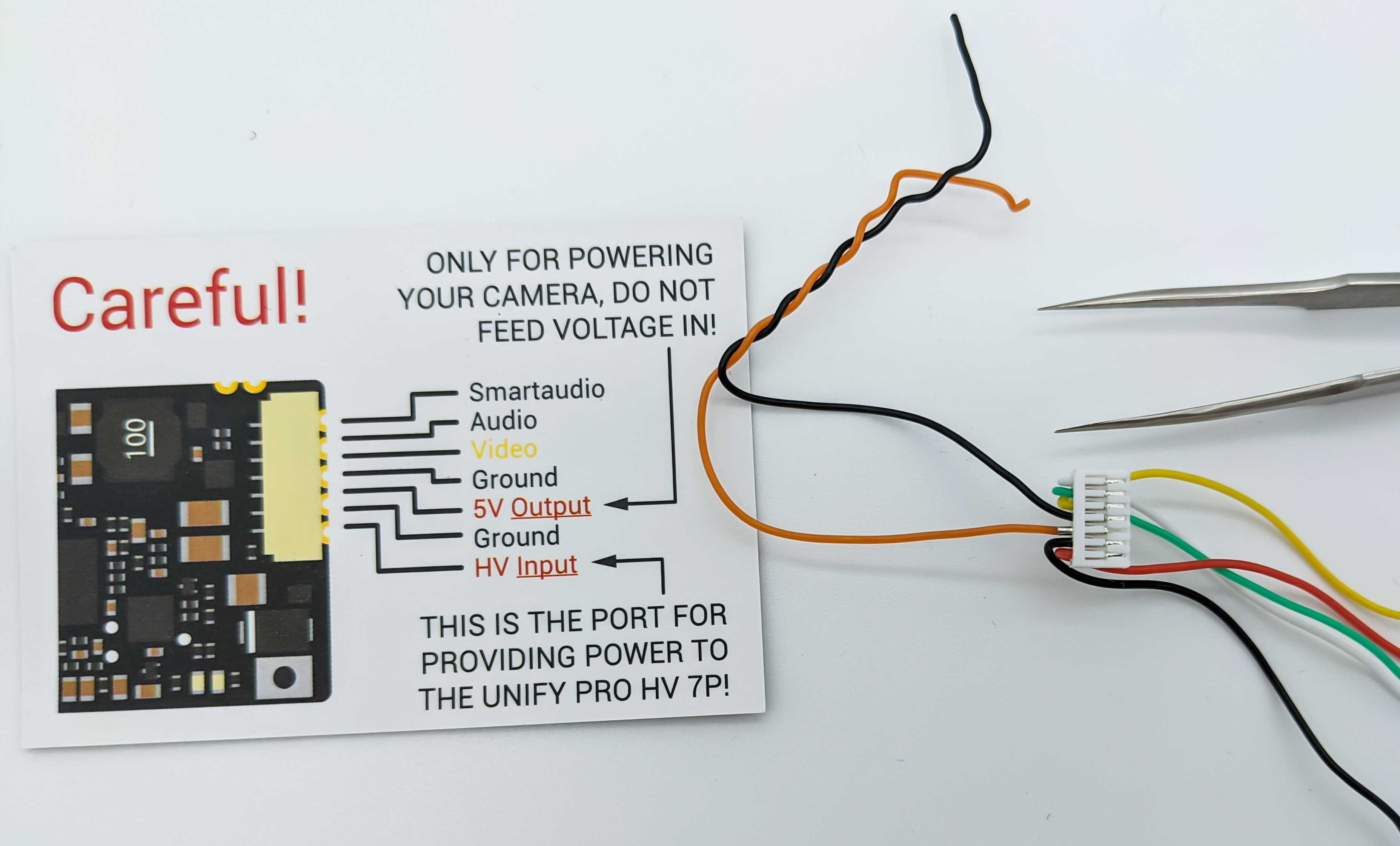
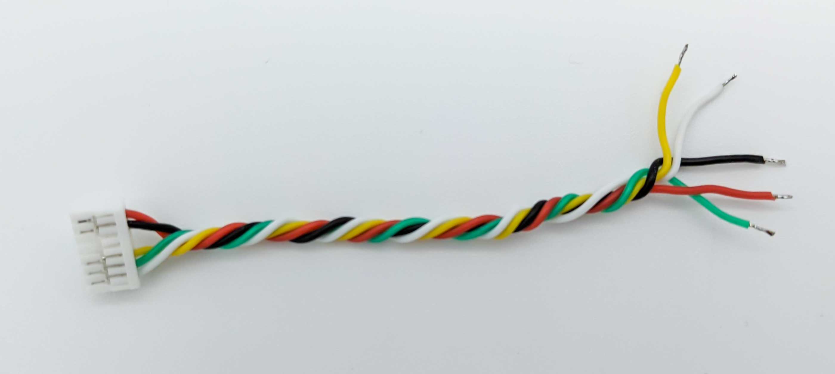
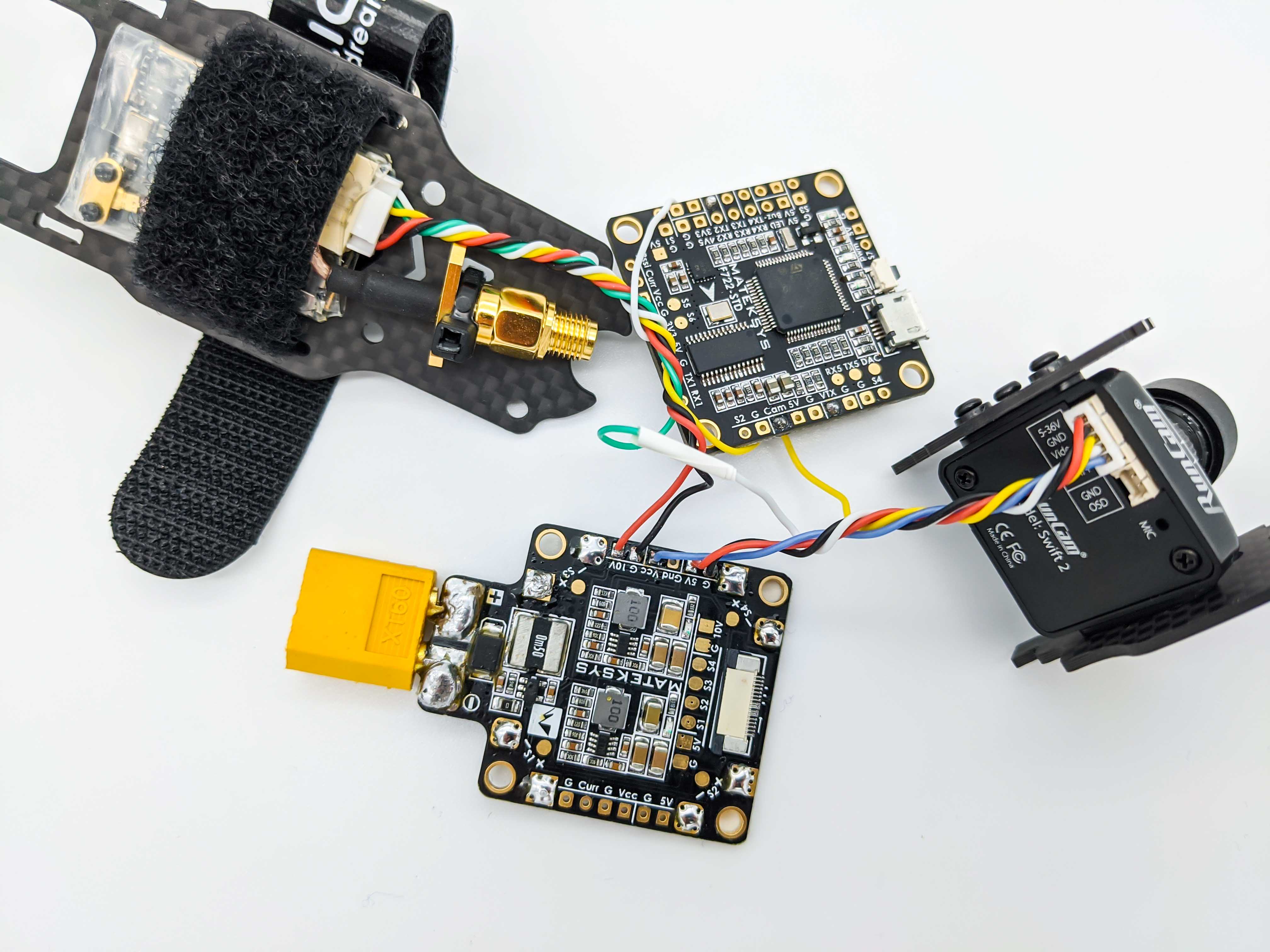
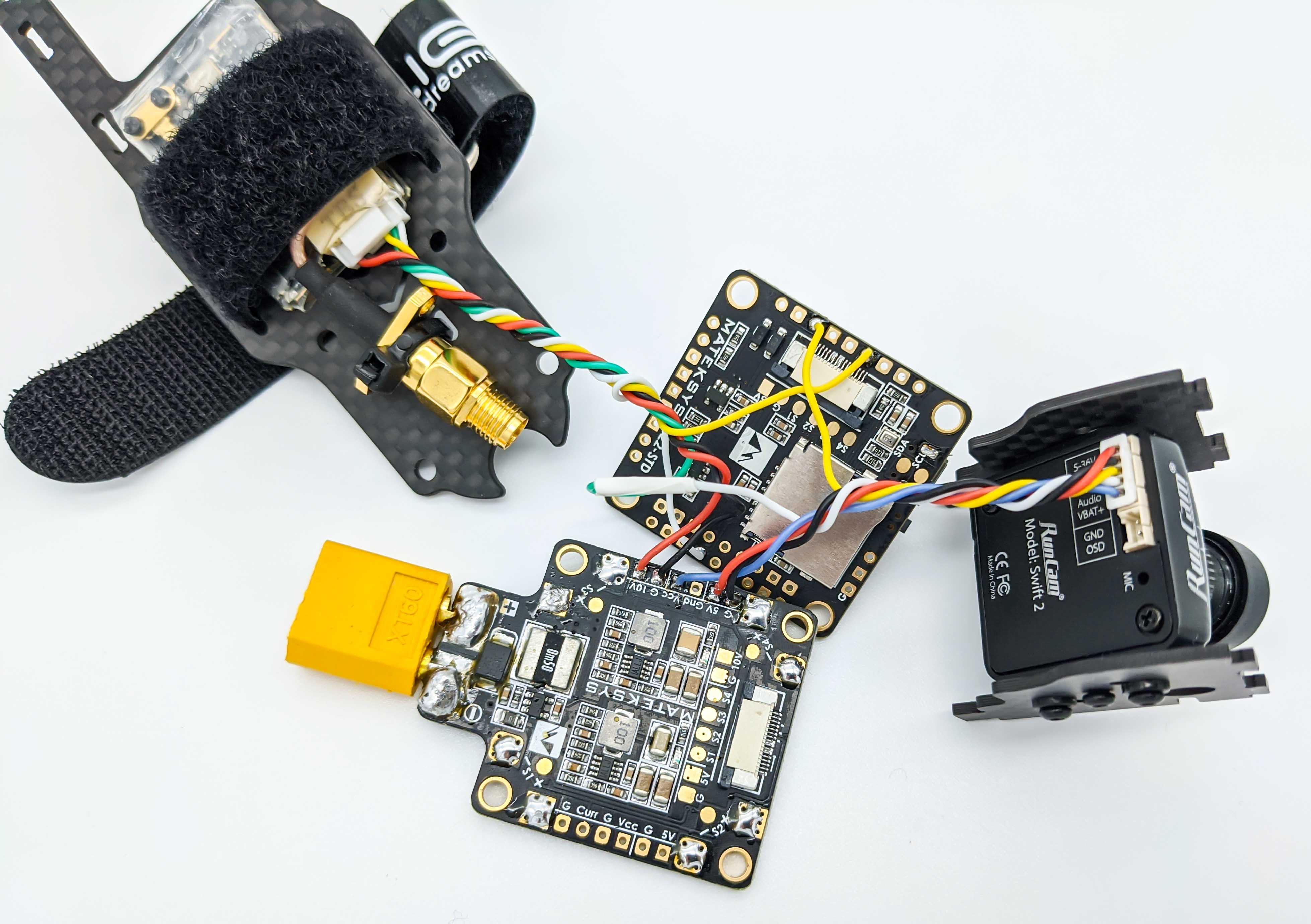
Next, we prepare the cable of the VTX by removing the power supply cables (plus 5V and Ground) for the camer. The reason for this is that the camera will be powerd over the PDB and not the VTX, which whould be possible too. However, this should reduce the heat of the VTX.
Install the Camera and the VTX
With the prepared cables of the camera and the VTX we look for suitable pins on the PDB and the FC.
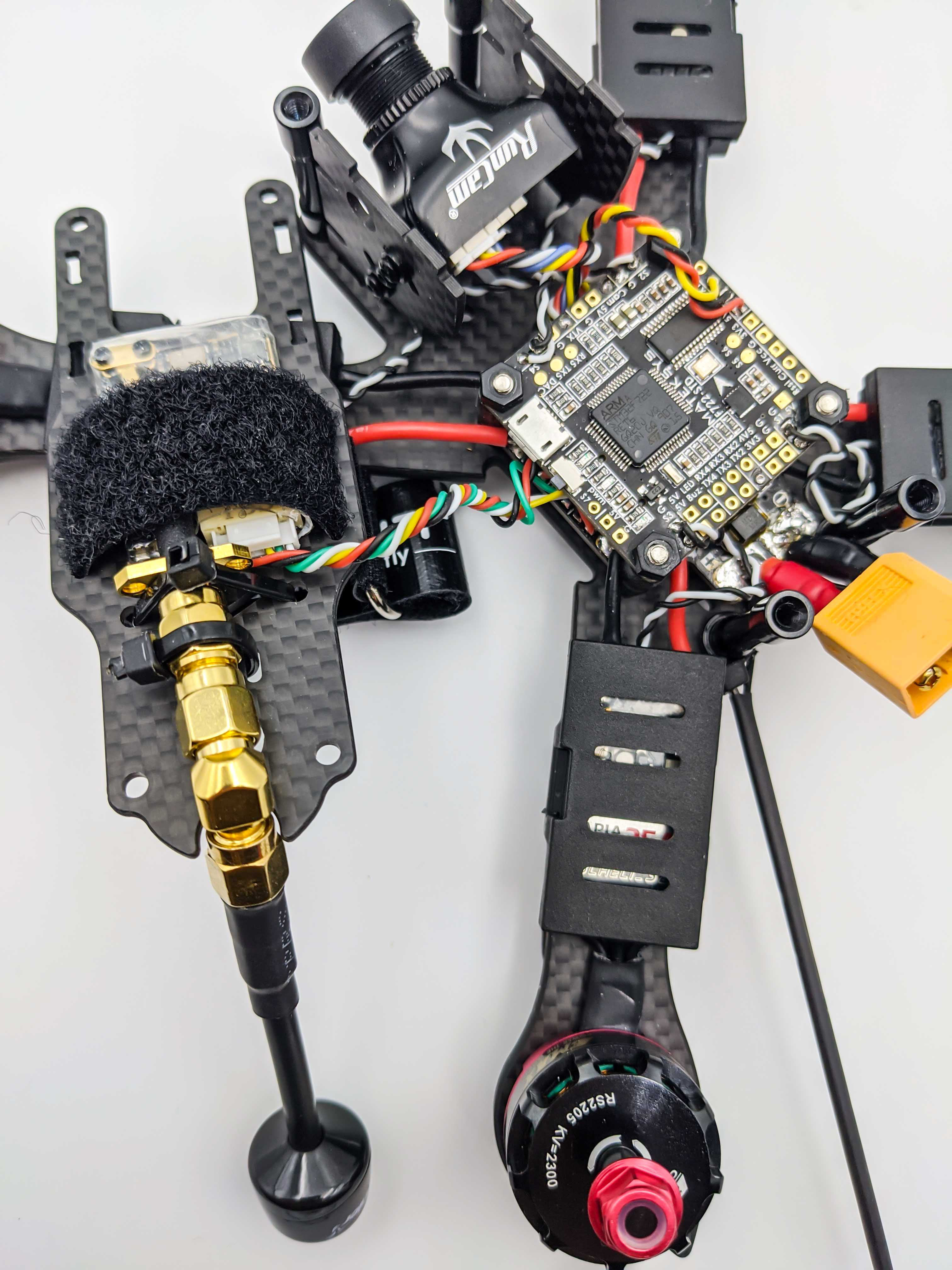
The following image shows the final placement of the camer and VTX in the frame. The VTX is mounted on the top plate of the iFlight frame.
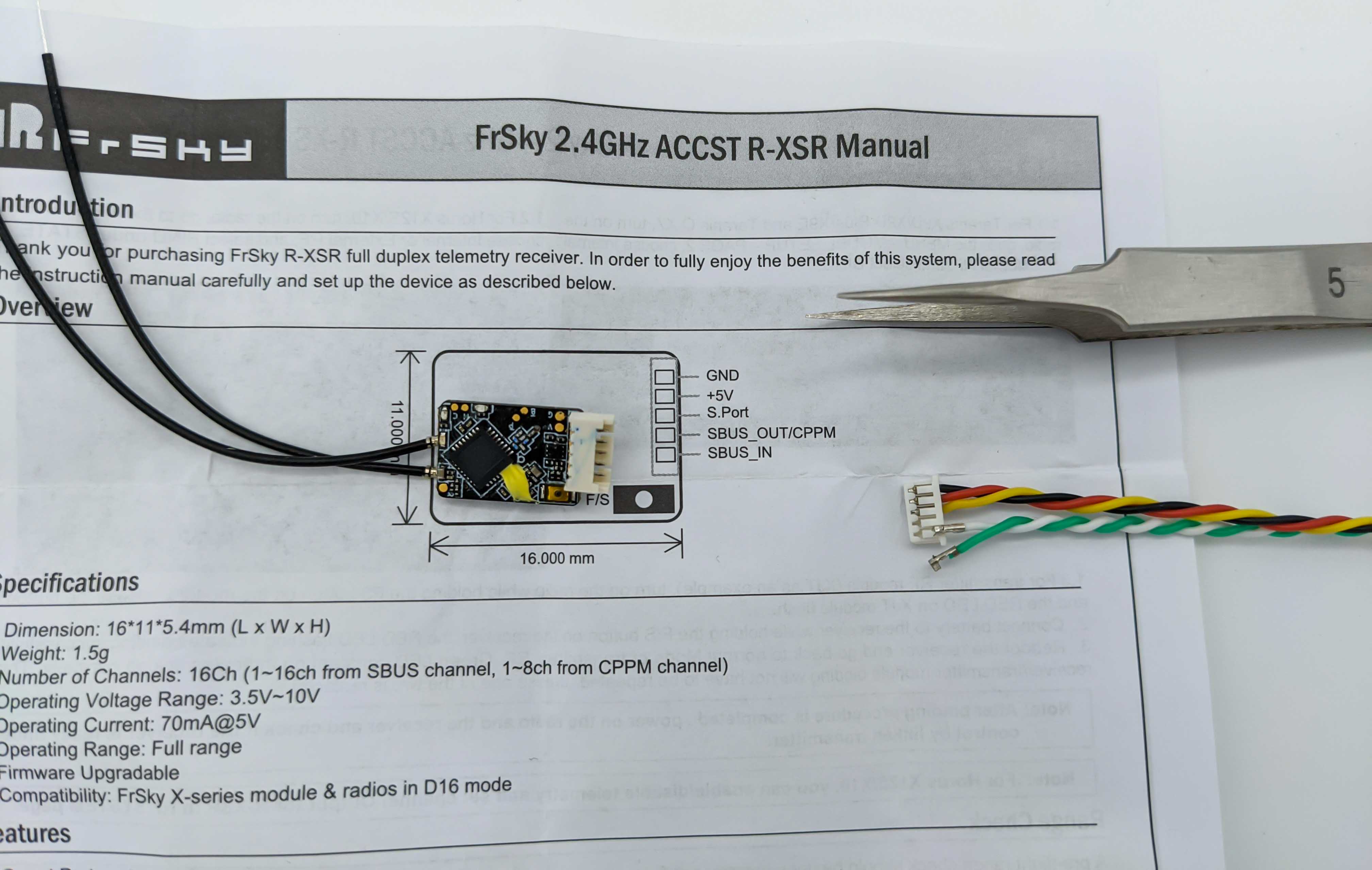
Prepare the Receiver
Place the receiver in the frame where won’t interfere with the propellers. Try to place it below the propellor line - where the propellers will spin - to avoid that the antennas get sucked into the propellers. This could happen if the antennas are mounted above the propellers and bend too much. The next section will show how to strengthen the receiver antennas which should make it possible to mount them also above the propeller line. However in the following setup the receiver is placed in the bottom of the frame which leads to the antennas being below the propellers.
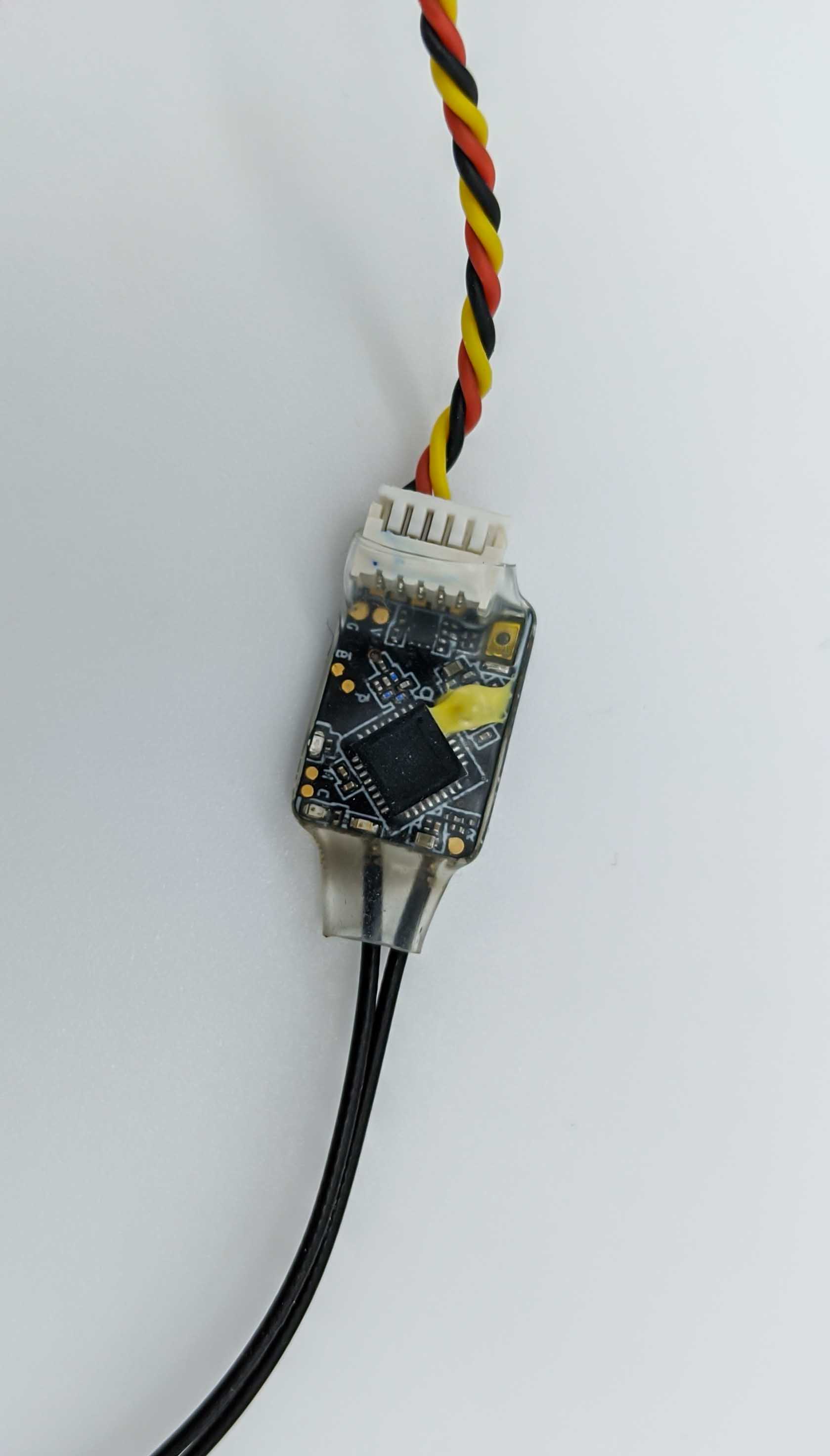
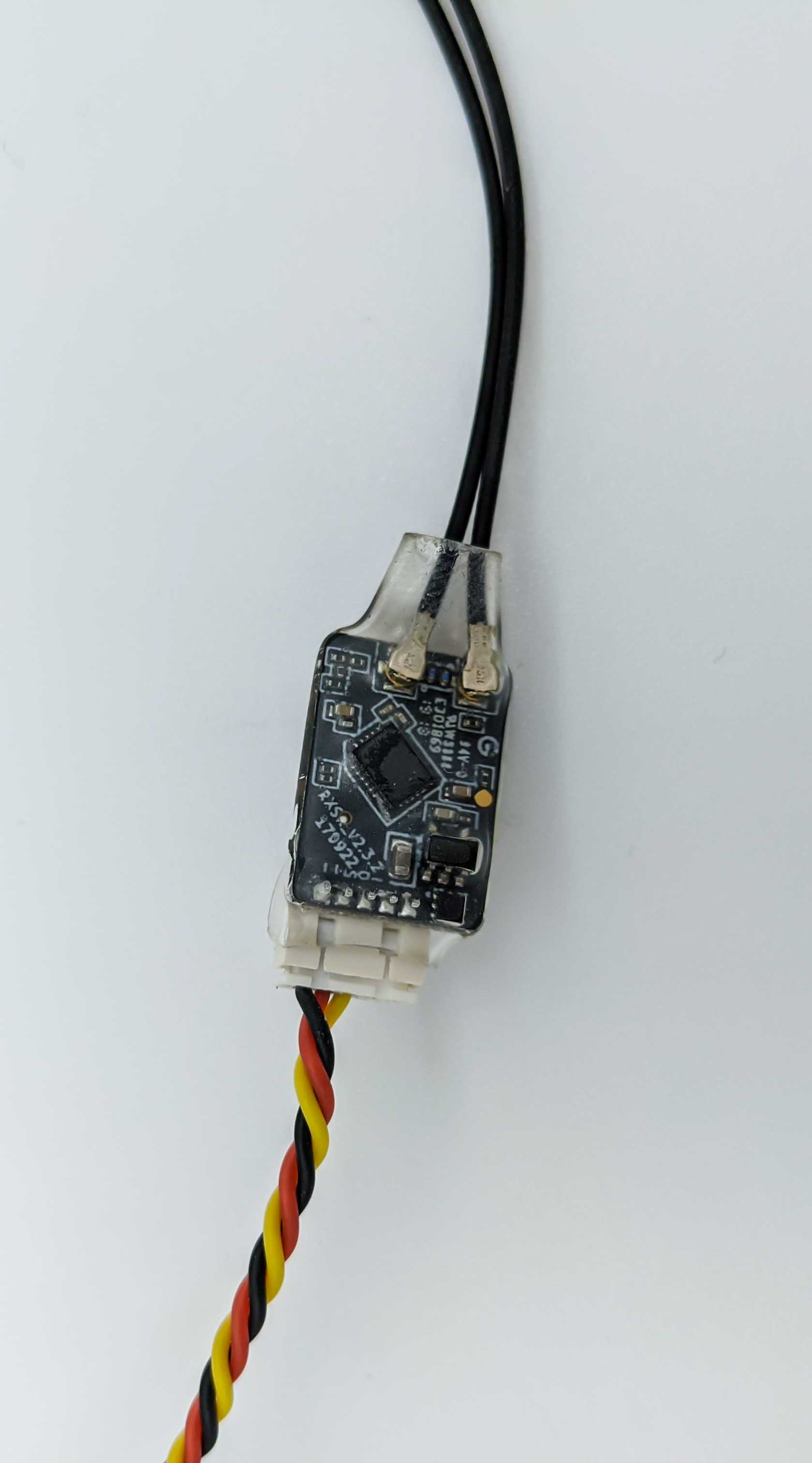
Next, we prepare the R-XSR receiver to use only its F.Port. Because we use only the F.Port we remove the input and output SBus cables.
After removing the SBus cables and applying a shrink tube, the receiver looks like this:
Connect the Receiver to the Flight Controller
The R-XSR receiver in this build is flashed with the FPort protocol which requires only one wire and thereby combines SBUS and Smarport Telemetry. For this, a receiver with an FPort firmware uses its SmartPort connector to communicate with the Flight Controller via one of its UART TX pins. In this build, TX1 is used. The receiver can get its power from the Flight Controller which is convenient when soldering because the Mateksys F722 FC has a TX pin right next beside 5V and Ground pins.
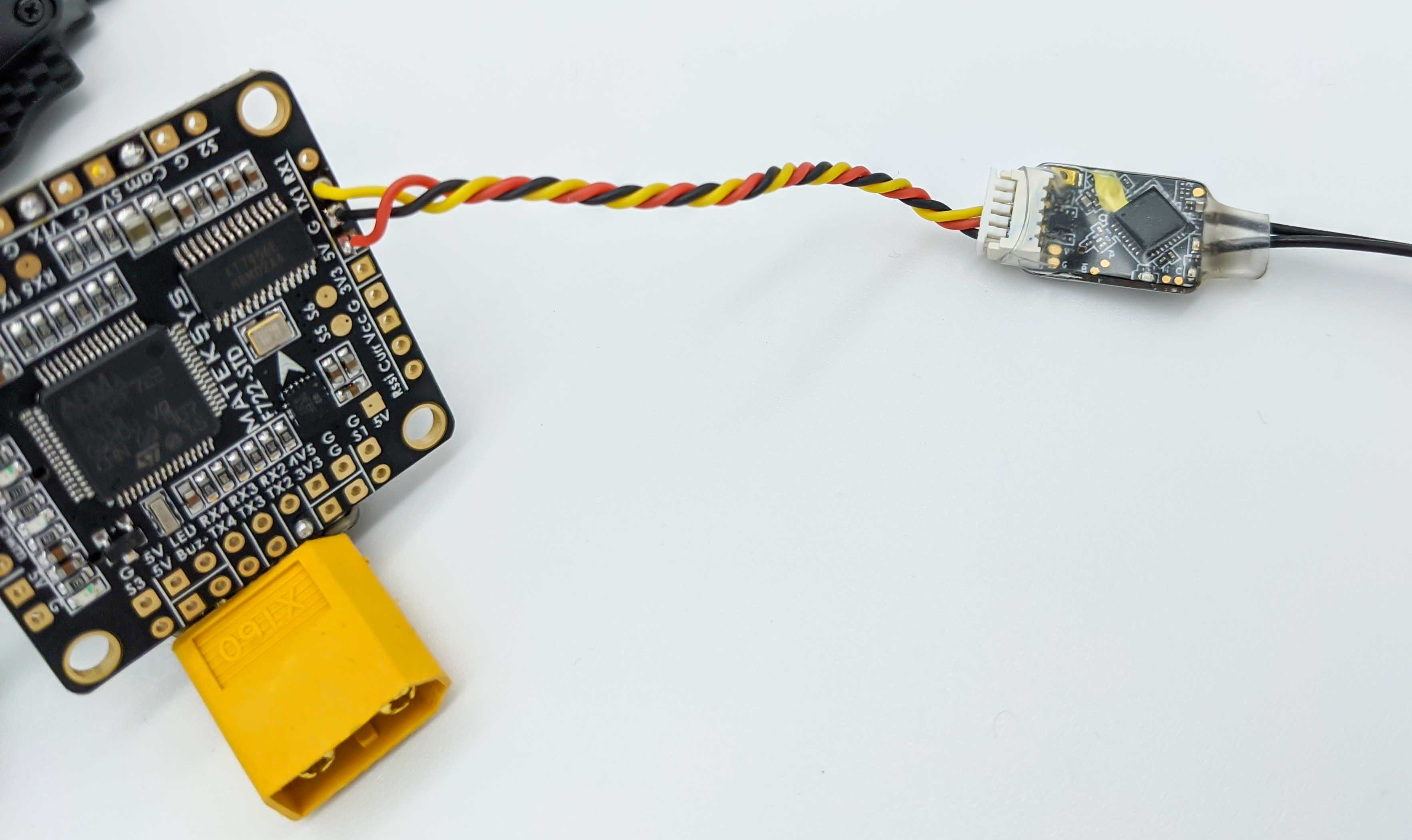
The SmartPort of Frsky receivers is an “inverted” signal which can’t be read direclty with F4 flight controllers. It’s no problem for F3 and F7 flight controllers and it can be direclty connected to one of the free UARTS TX pins, shown above.
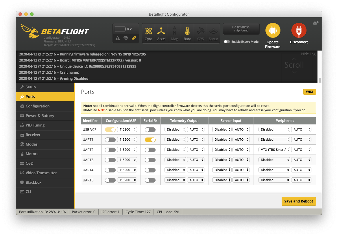
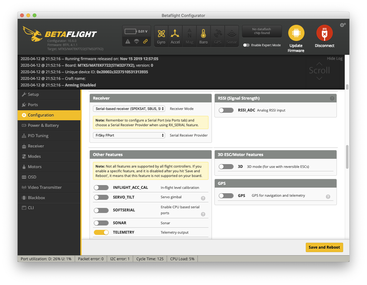
To configure FPort in Betaflight it is necessary to adjust settings in the Configuration and Ports tab:
- Configuration: In the “Receiver” section select “FrSky FPort” as “Serial Receiver Provider”. Telemetry can be enabled in the section “Other Features”.
- Ports: Enable “Serial Rx” for the UART identifier which is connected with the SmartPort of the receiver.
Because SmartPort (and also FPort, which is the same physical port on the receiver) is an “inverted” signal it is required to enter the following commands in Betaflight’s command line interface (CLI) when using F3 or F7 flight controllers:
set serialrx_halfduplex = ON
set serialrx_inverted = ON
save
After successfully setting up the receiver in Betaflight and binding the receiver with the transmitter we should verify the control inside the Betaflight’s “Receiver” tab:

Moving the control sticks and the sliders should be visible inside Betaflight.
The final placement inside the quadcopter will look like in the following image, which makes it possible to press the (small) F/S button on the receiver. This button is also used to bind the receiver.
To setup telemetry on the Taranis X9D Plus navigate to the Telemetry Page. To get there, short press “Menu” button on the Taranis and then “Page” until you reach the Telemetry Page.
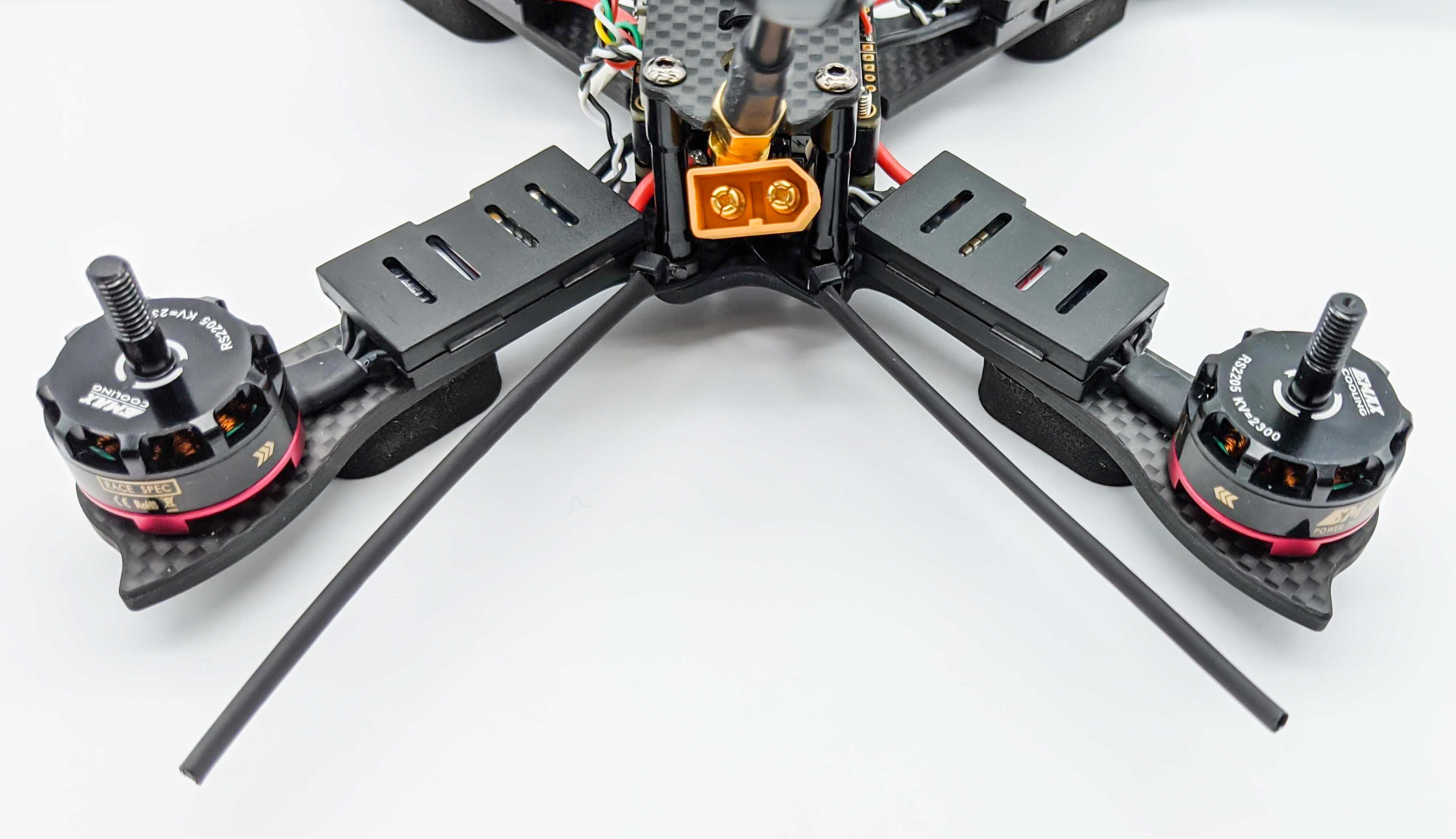
Receiver Antennas
The following shows how to strengthen the antennas of the receiver to avoid bending too much and a possible collision with the propellers. Also make sure not to fixate the antennas too close to the frame, because it would lead to reduced signal strength (lower RSSI).

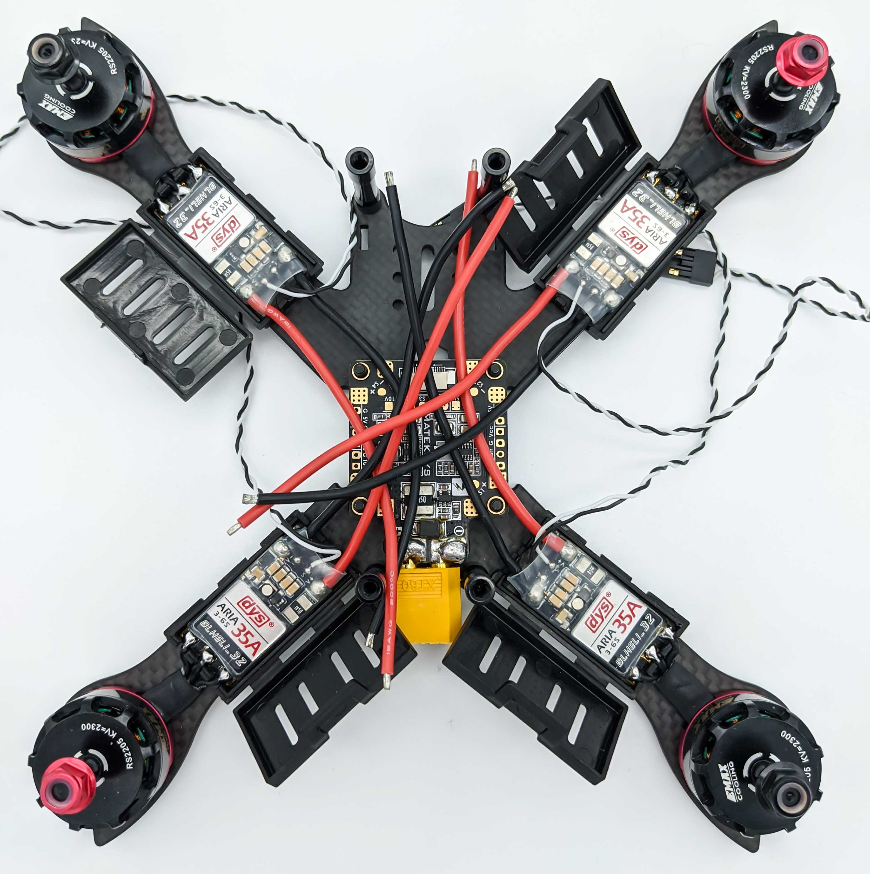
Connect ESCs to the PDB
One of the last steps is to tin the PDB pads that are going to power the ESCs using four power (red) and ground (black) wires. This should be one of the last steps because the power wires will fix the PDB to the frame and this makes it harder to solder other components that require power from the PDB, such as the VTX system, installed in the previous steps.
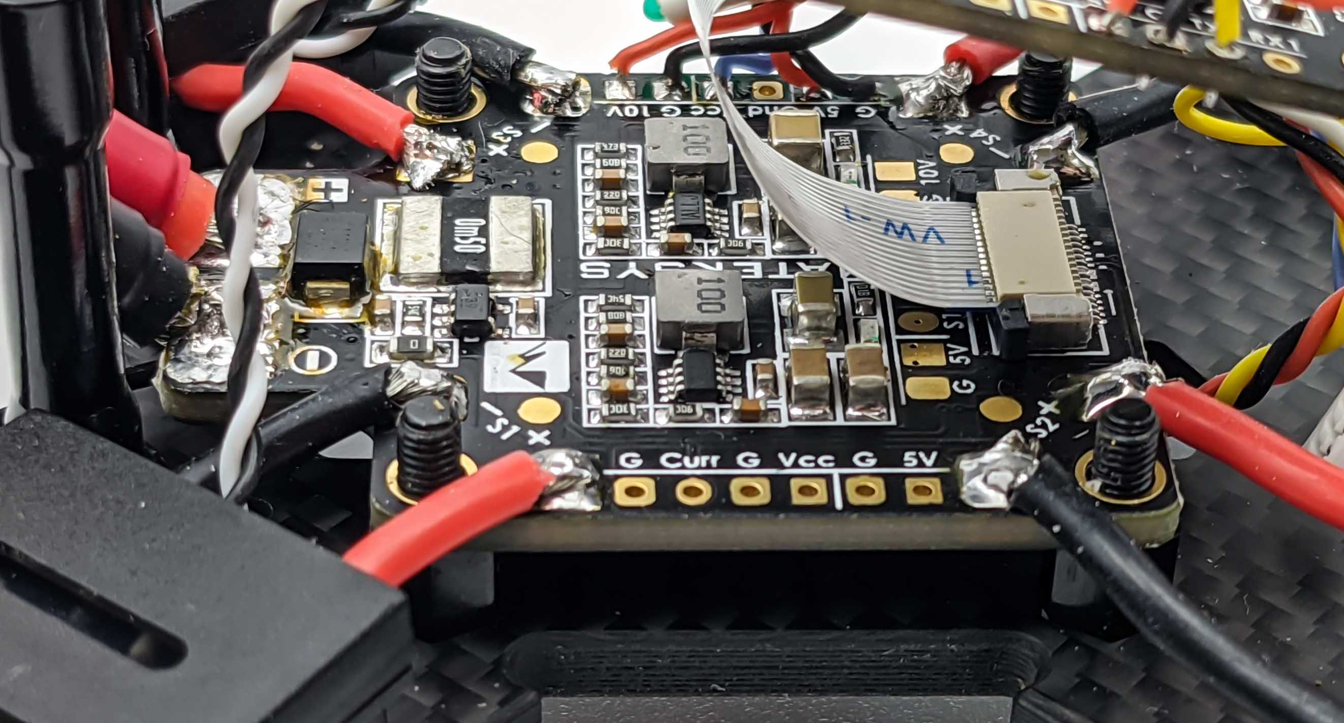
To control the ESCs they are connected to the Flight Controller signal pins S1 to S4 each with its own Ground connector. The FC is placed above the PDB using rubber standoffs to reduce vibrations that can disturb the inertial measurement unit (IMU) of the FC.
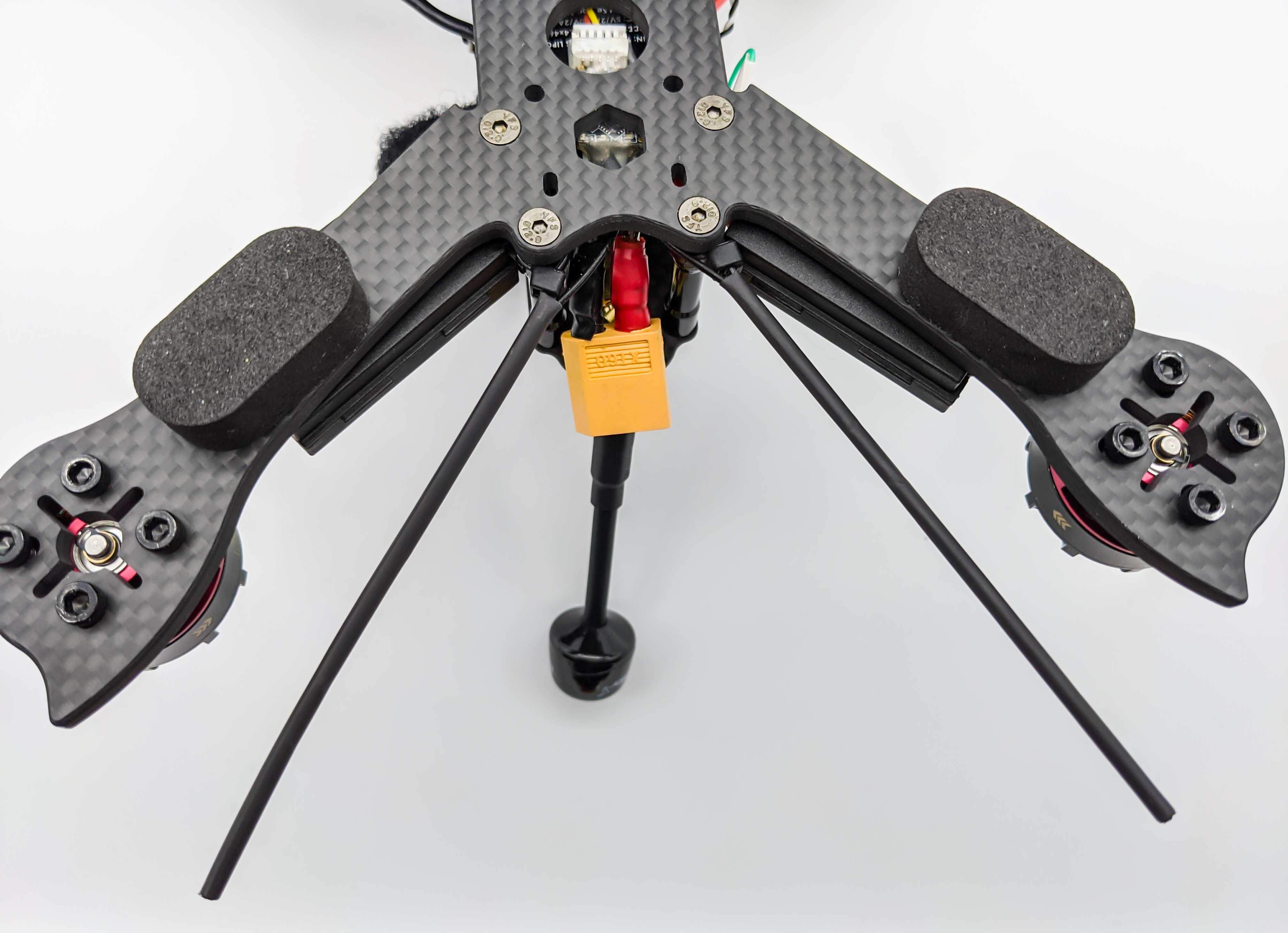
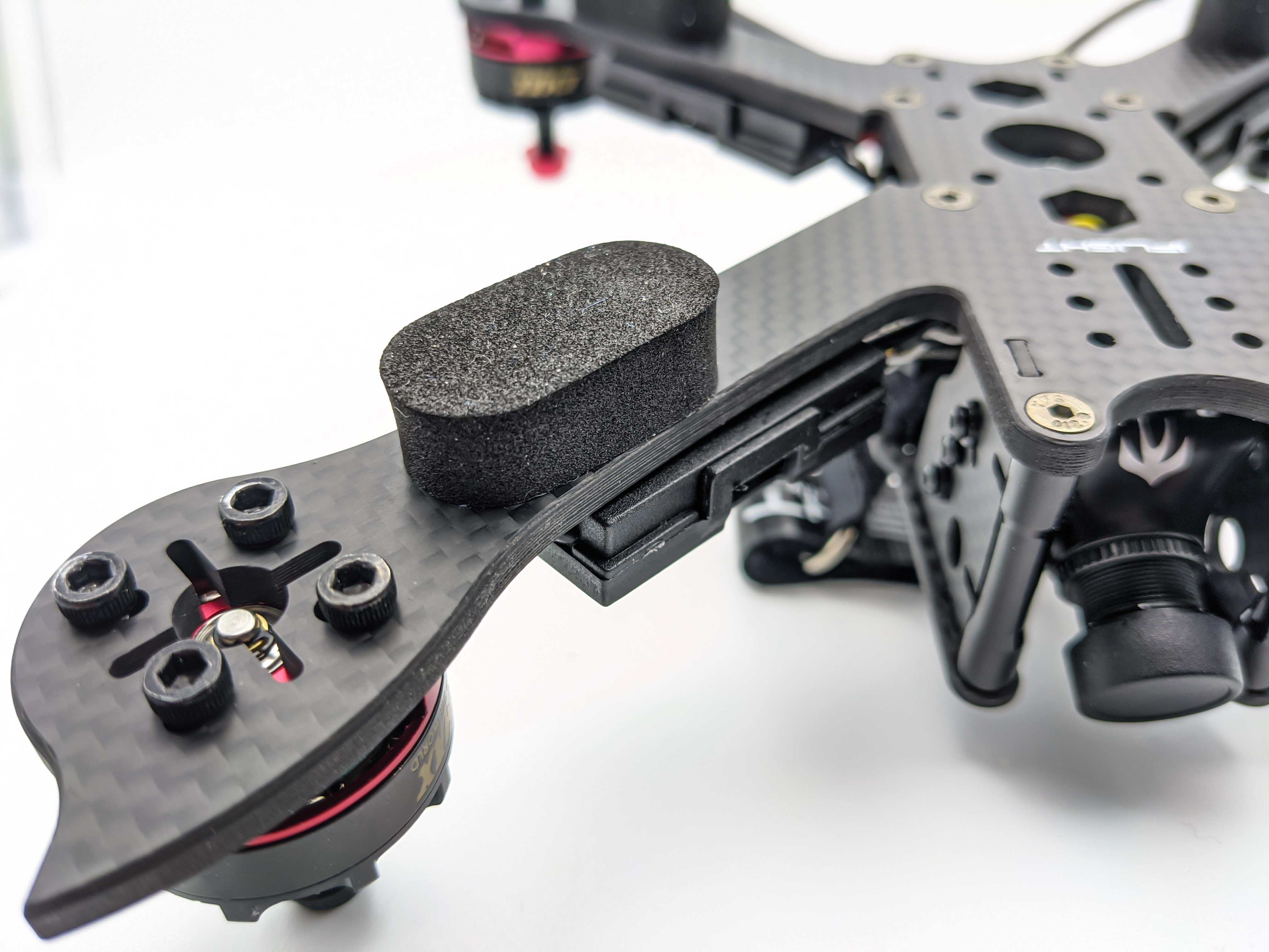
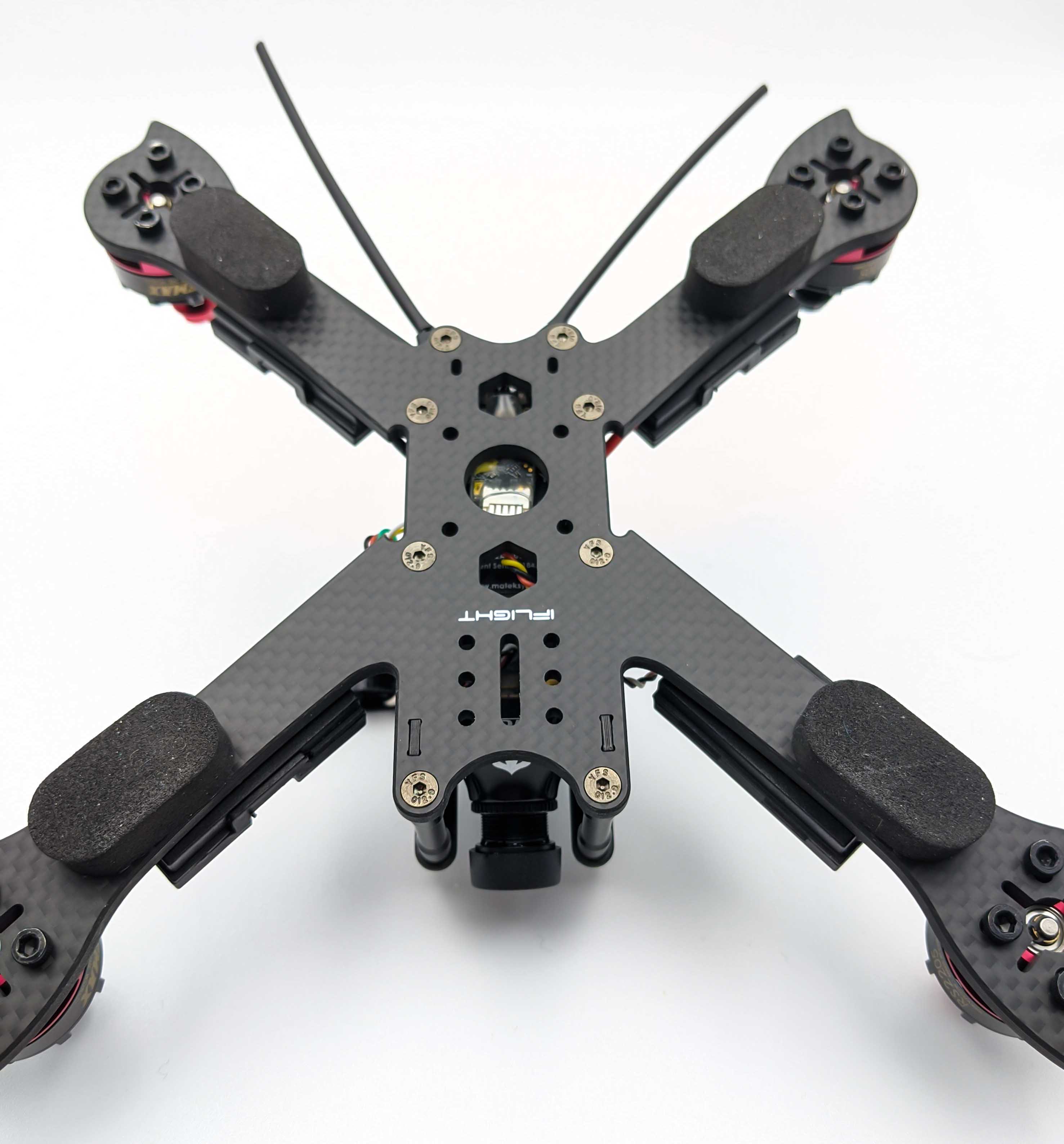
Landing Pads
To avoid scratches on the bottom of the carbon fiber frame we apply soft foam landing pads:
Comments