In small drones it is not always possible to provide power via different wiring harness, additional devices like UBEC or further voltage regulators. Instead, in such cases a space-saving component is used, known as Power Distribution Board (PDB) which takes care of distributing the energy from the battery to all other parts of a copter.
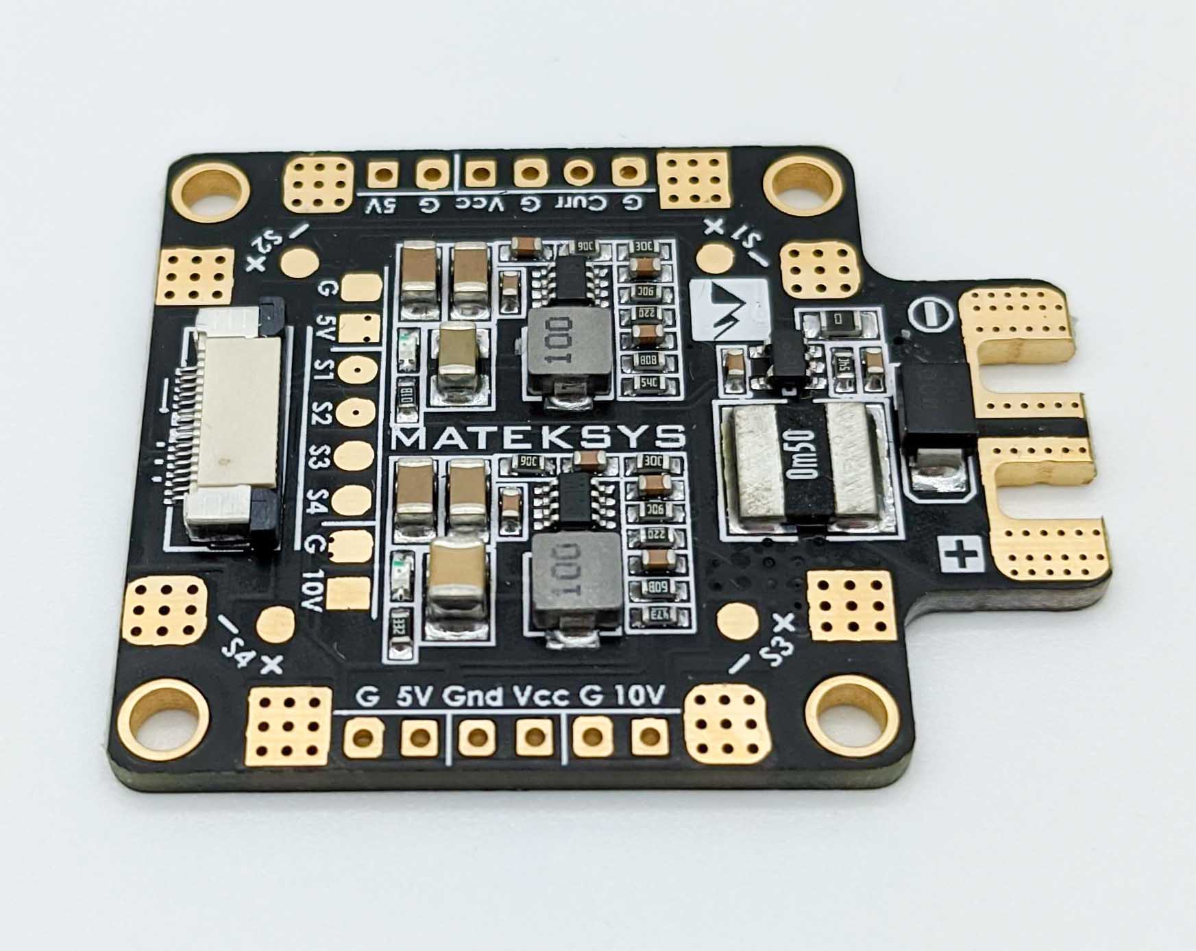
This device is specifically designed to operate in small drones because of its small form factor and variety of connectivity options. First and most important is the battery connection, which is where the flight battery is connected and the power is distributed. The second important connection is to the ESCs. These connections are soldered to the PDB. Depending on its specification level, a PDB has further connections for FPV sender and LEDs, which partly operate on different voltage levels. Therefore, PDBs exhibit different voltage outputs such as 5 volt and 12 volt.
When selecting a PDB the highest possible current load has to be respected. During a FPV race often high currents are flowing which can be above 100 A. In case a PDB tolerates only 80 A it will heat up during a race which can damage the PDB and then lead to a crash. Therefore keep the maximum current draw of the motors in mind and that the selected PDB can handle it.
The Matek FCHUB-6S of this Build
This build uses the Matek FCHUB-6S power distribution board. It distributes the power of a 3S to 6S LiPo battery to the four ESCs, provides regulated 5 V and 10 V outputs and measures the current drawn from the battery.
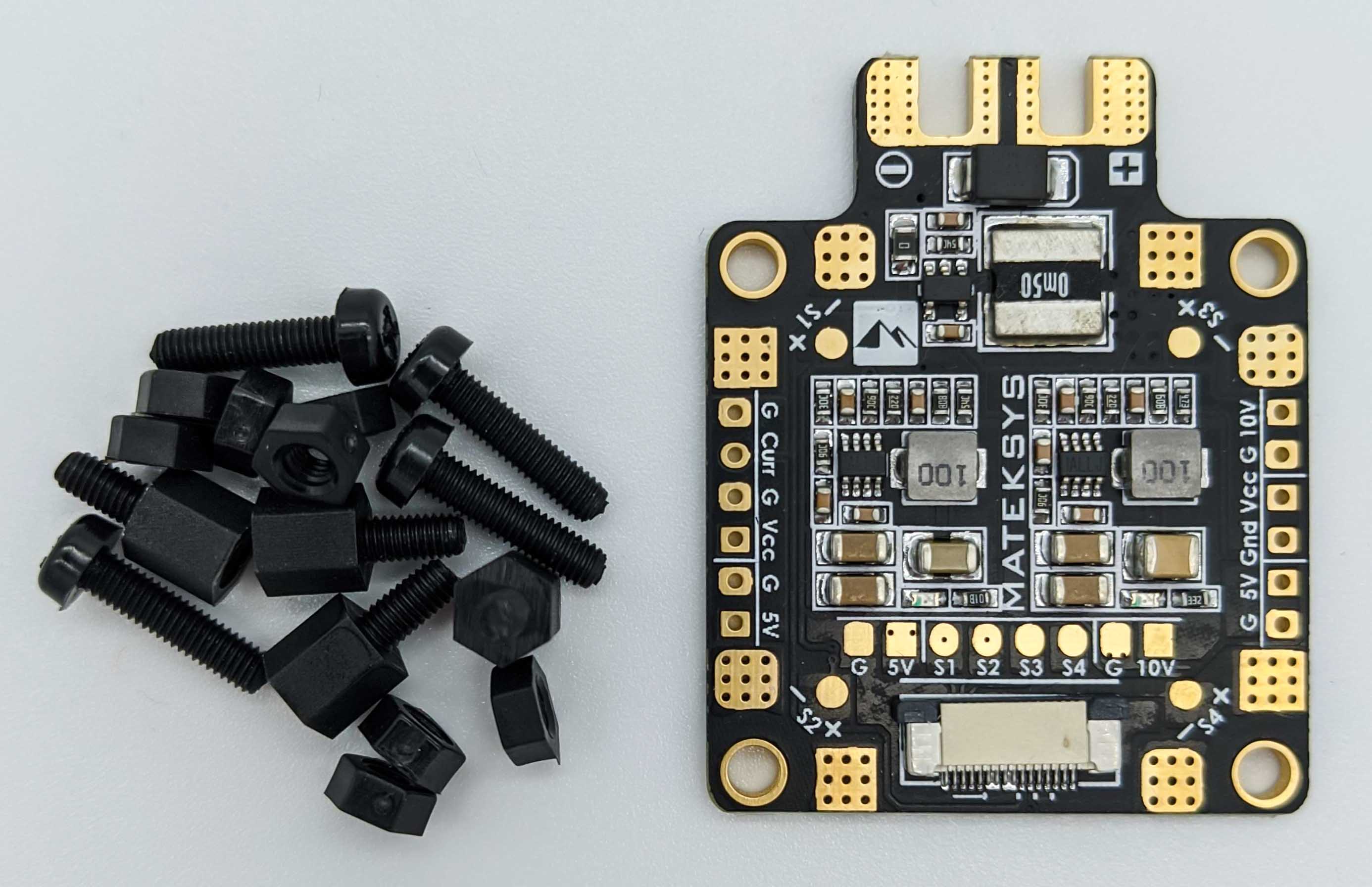
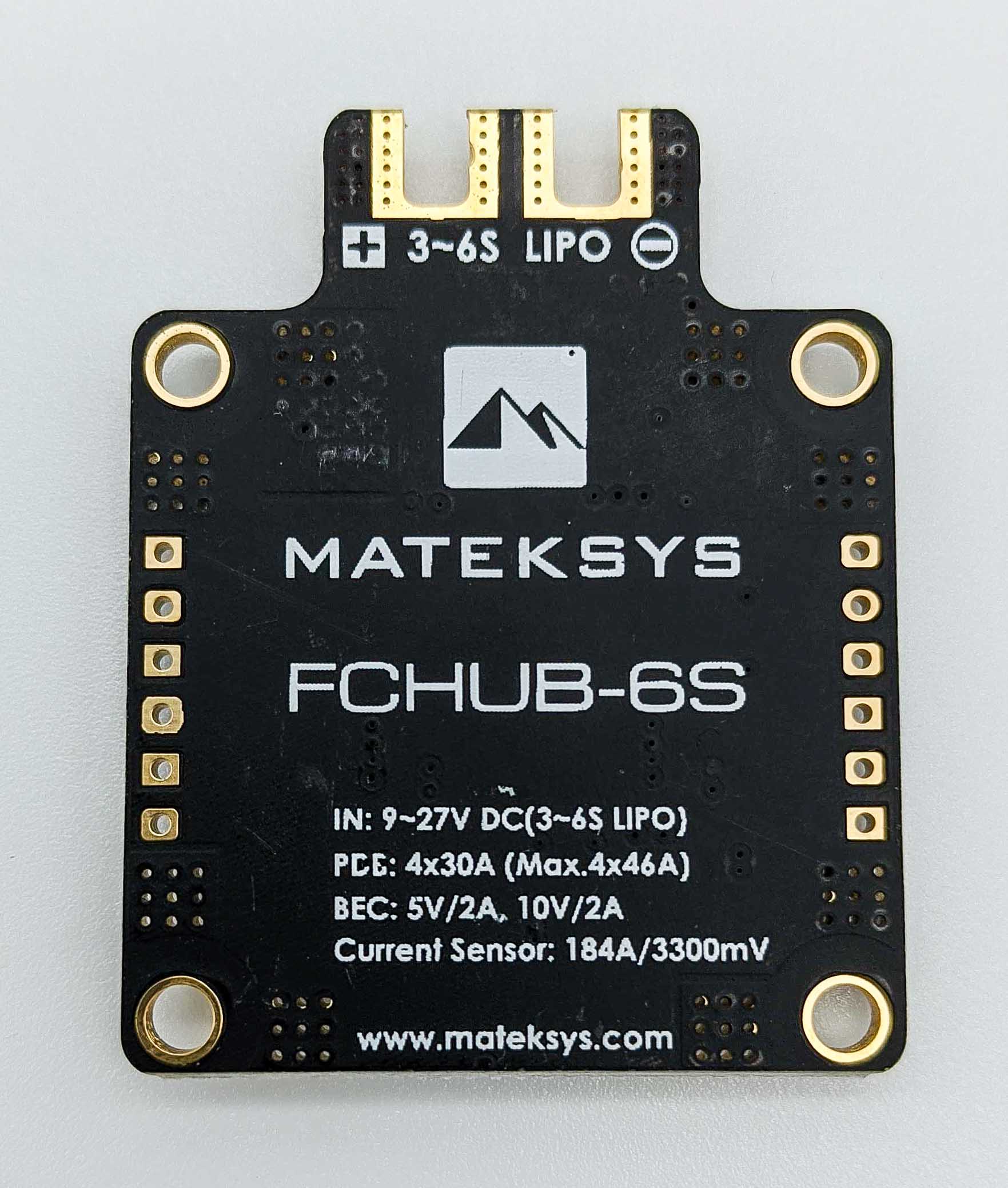
According to the manual, it has the following specifications:
| Property | Value |
|---|---|
| Input | 3S to 6S LiPo, up to 27 V, with TVS protection against voltage spikes |
| ESC outputs | 4 pairs of solder pads for X frames, 4 × 30 A continuous (4 × 46 A for 5 seconds) |
| BEC 5 V | 1.5 A continuous (2 A for 10 seconds per minute), for flight controller, receiver and OSD |
| BEC 10 V | 1.5 A continuous (2 A for 10 seconds per minute), for video transmitter and camera |
| Current sensor | Up to 184 A, 3.3 V analog output |
| Mounting | 30.5 × 30.5 mm hole pattern, 3 mm holes |
| Dimensions and weight | 36 × 46 × 4 mm, 8.5 g |
BEC Outputs
Both outputs are DC/DC converters (a BEC on the board), so no separate UBEC is needed. The 5 V output powers the flight controller, the receiver and the OSD. The 10 V output is meant for the video transmitter and the camera, and it also works with cameras labeled for 12 V. Matek notes that on a 3S battery the input voltage should stay above 11 V for the 10 V output. A 3S pack drops below that towards the end of a flight, so the 10 V output can then fall slightly below 10 V.
Current Sensor
The current sensor measures the current that flows from the battery to the ESCs. Matek flight controllers such as the F722-STD of this build connect to the board with a flat flex cable (FFC) instead of single wires, and the flight controller reads the sensor with its analog-to-digital converter. Betaflight then shows the current draw and the used capacity in mAh, for example in the OSD. To set it up, select the onboard ADC as current meter source in the Power & Battery tab of the Betaflight Configurator and set the scale to 179, the value Matek specifies for this board.
Comments