The motors of a copter convert the electrical energy of the battery into mechanical engergy that spins the propellors attached to the motor shaft and therefore results in kinetic energy of the drone. With a suitable propellor attached this energy makes it possible to reach speeds up to 130 km/h.
Electromagnetism
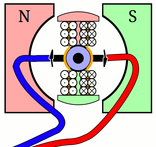
Electric motors of both types, brushed and brushless, use the same principles of electromagnetism to convert electrical energy into rotation. If a voltage is applied to a copper wire, a current will flow, which will induce a magnetic field. With a permanent magnet near this current-carrying copper wire it is possible to generate linear or rotational forces to the wire and the magnet.
Brushed DC Electric Motor
Some years ago brushed motors were used in rc plane models, which have a big disadvantage. As the name suggests, brushed dc motors require carbon brushes, which make contact to the rotating rotor to enable the flow of current. The brushes of a dc motor are made of graphite which is a wearing part that reduces the efficency. Another disadvantage are sparks, which can disturb or damage other electrical components. Because of the constant stress that these parts have to endure in a multicopter, they would need to be replaced often.
A brushed dc motor consist of multiple parts, that act together, to create a rotation: a static part, called the stator, and a rotating part, which is the rotor. Permanent magnets with alternating polarity are attached to the stator. The rotor also known as armature, which consists of a soft iron core that is wrapped by a copper coil.
A current that flows through the coils of the armature produces a magnetic field $\vec{B}$, which has a north and a south pole. The orientation of the poles is in accordance to the direction of the current. To achieve a rotation of the rotor the magnetic orientation of the current-carrying coil has to be directed, such that the repulsion and attraction of the magnetic fields between stator and rotor generate a permanent rotation. The problem is to keep the rotation by changing the poles of the copper coils - commutate. To achieve this a commutator is used. During the rotation of the rotor, its purpose is to switch (commutate) the direction of current flow and therefore to change the direction of the magnetic field. This makes the commutator an electrical switch. The current has to be transfered of a static part onto the rotating commutator, where the previously mentioned brushes are used. These are made of graphite and are in light contact with the commutator through a spring.
Brushless DC Electric Motor
As the name suggests, brushless dc motors require no wearing brushes for their construction. The commutation occurs electrically, not mechanically. In this case commutation is the interchange of the current through the coils to make the motor spin. The reason that no brushes are necessary for the flow of current, is that the change in direction of the current is happening on the stator. Therefore the current doesn’t have to be transfered to the rotating rotor, which aleviates the wearing parts - the brushes and the commutator. The current-carrying copper coils are wound around the stator sleeve. Attached to the rotor bell are permanent magnets in alternating polarity, which are often made of neodymium.

Neodymium is a chemical element in the periodic system with the symbol Nd and atomic number 60. It belongs to the lanthanide series and is a rare-earth element. Magnets manufactured from this element, count to the strongest magnets on earth.
For a brushless dc motor to work, it requires three phase wires instead of two in the case of a brushed dc motor. The three phases carry AC current where each phase is shifted by 120 degrees. This way the current direction and therefore the direction of magnetic fields are changed, which leads to repulsion and attraction with the permanent magnets that are attached to the rotor.
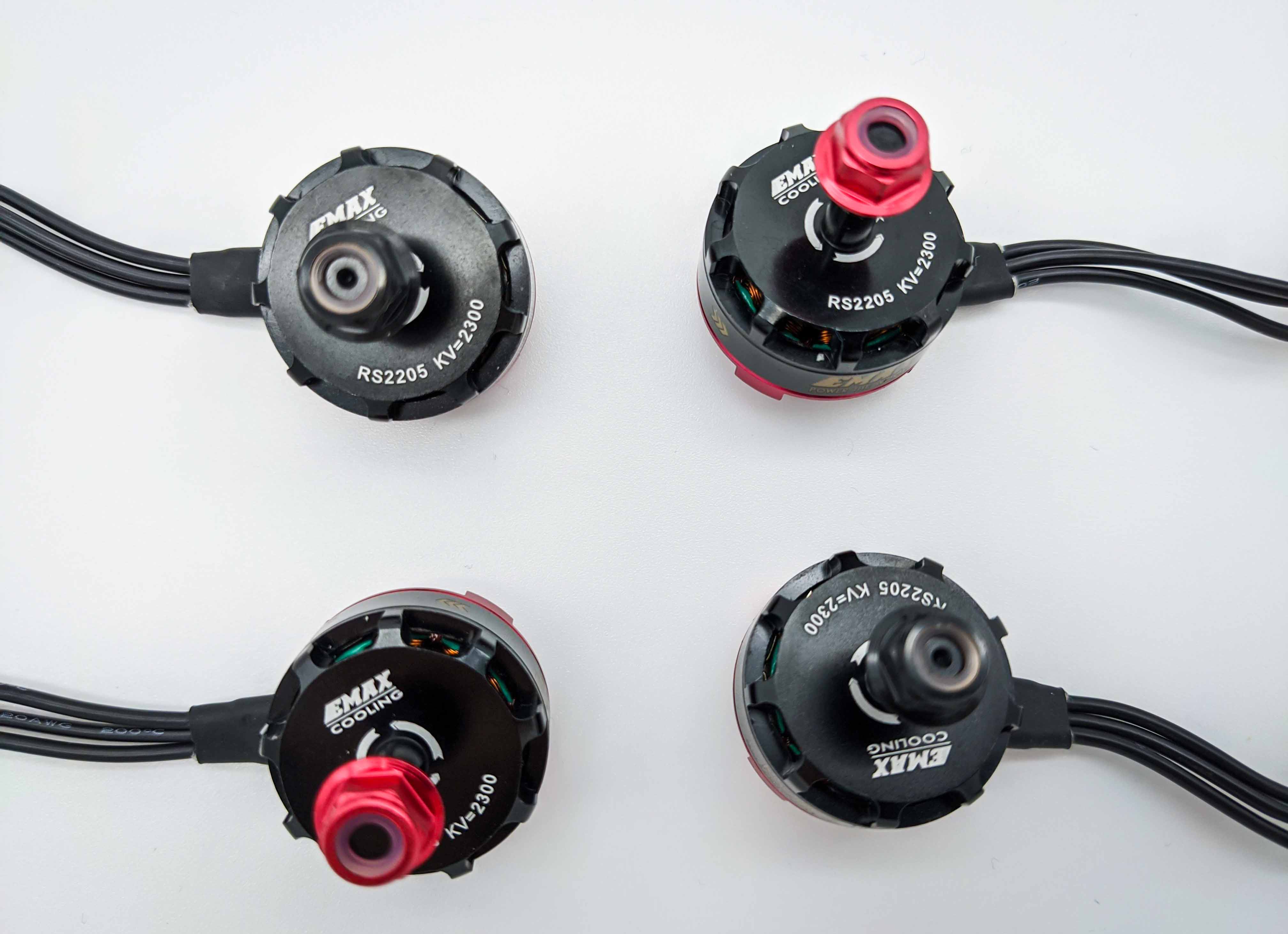
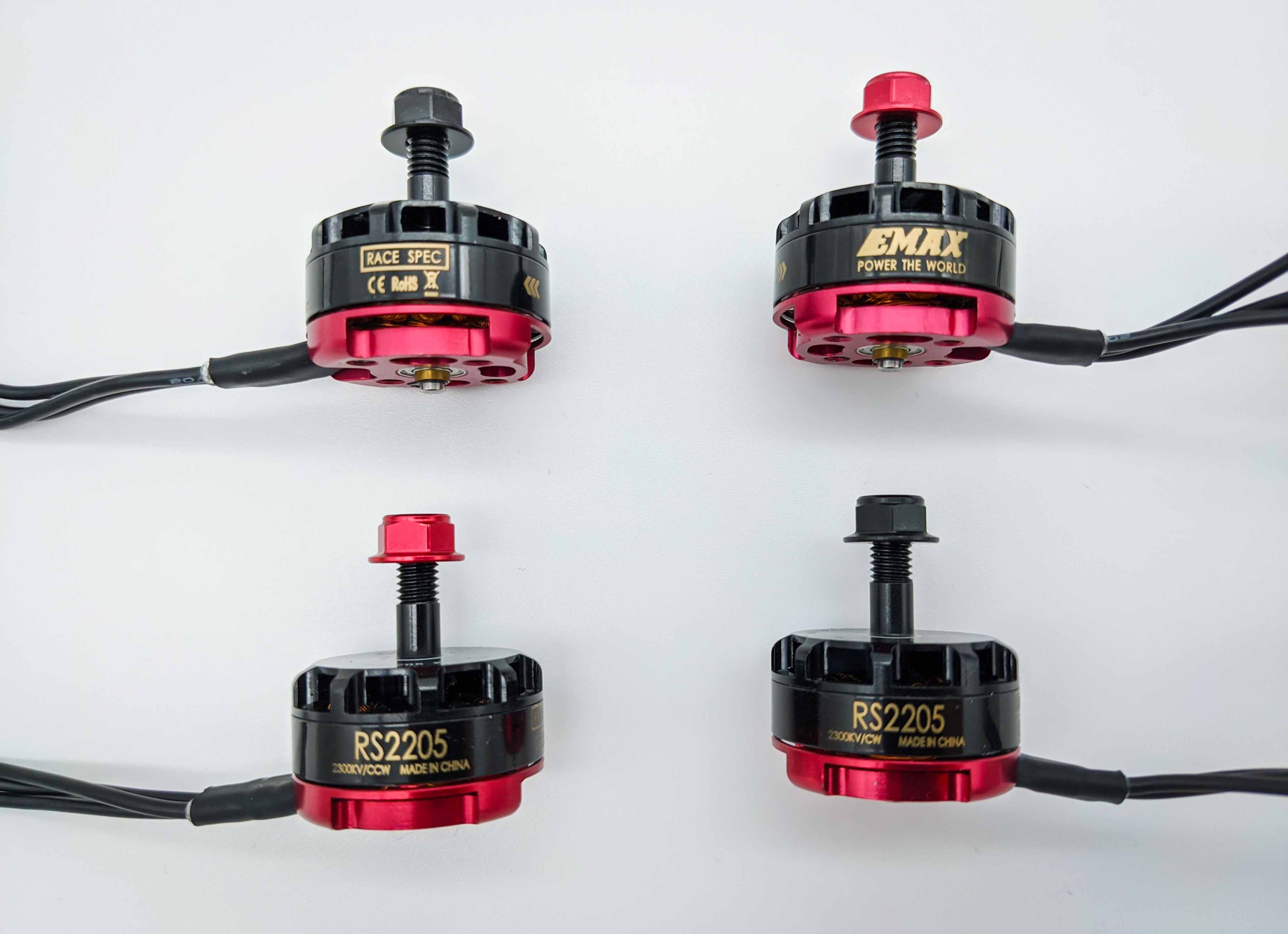
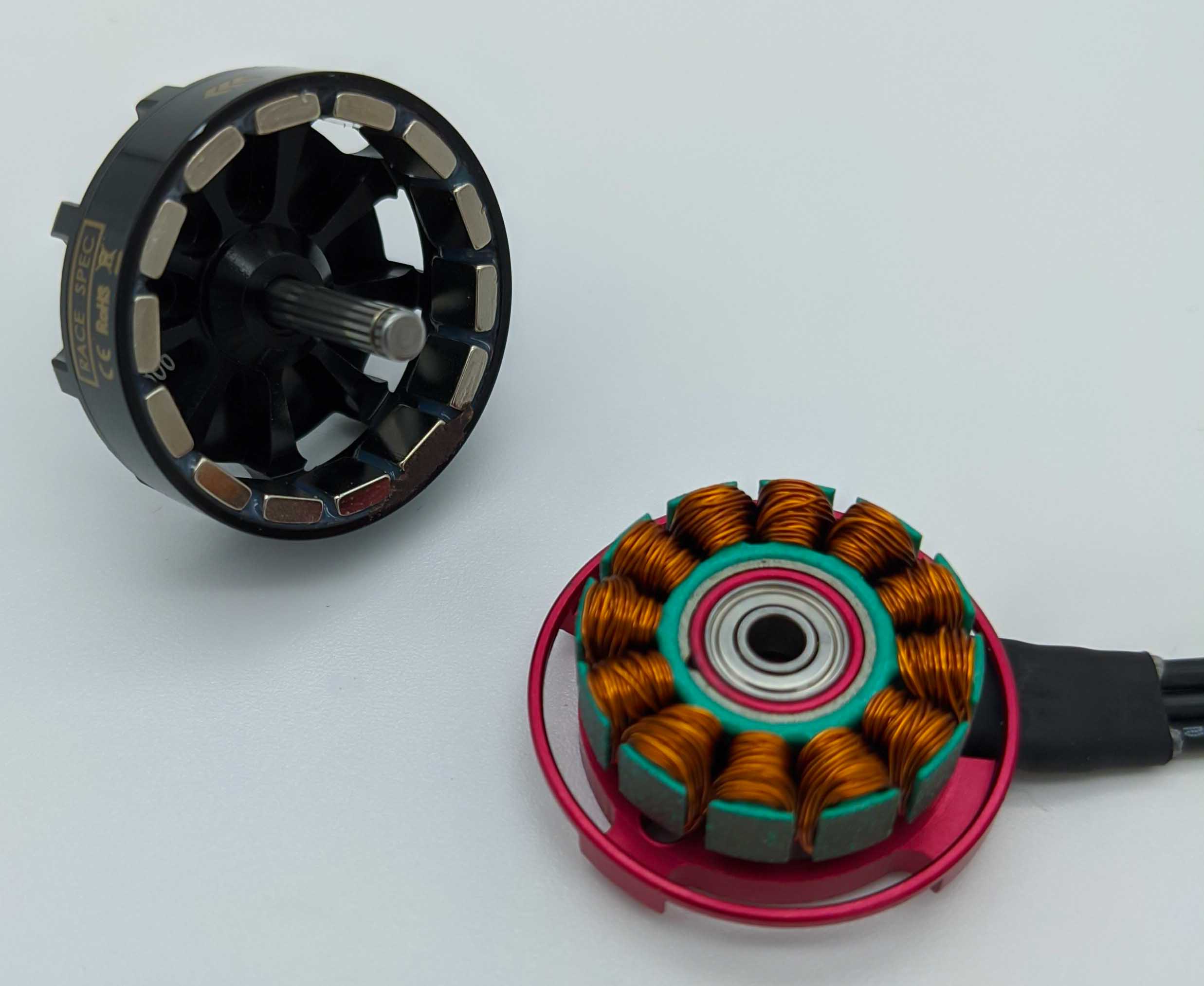
Outrunner vs Inrunner
Brushless motors are distinguished into outrunners and inrunners, which defines how they are designed. Inrunners have their static part (stator) outside and the rotating part (rotor) inside. This principle is the same as found in brushed motors. The opposite is true for an outrunner. The rotating part lies outside, the fixed part is inside. Outrunners are used for multicopters, because of their properties and metrics.
Compared to inrunners, outrunners often have a smaller $K_v$ rating, which is why they rotate slower (lower rpm) but have a higher torque and don’t need a gearbox. Inrunners are far too fast for most aircraft propellers, which is why they are used in conjunction with a gearbox.
Metrics of a Brushless Motor
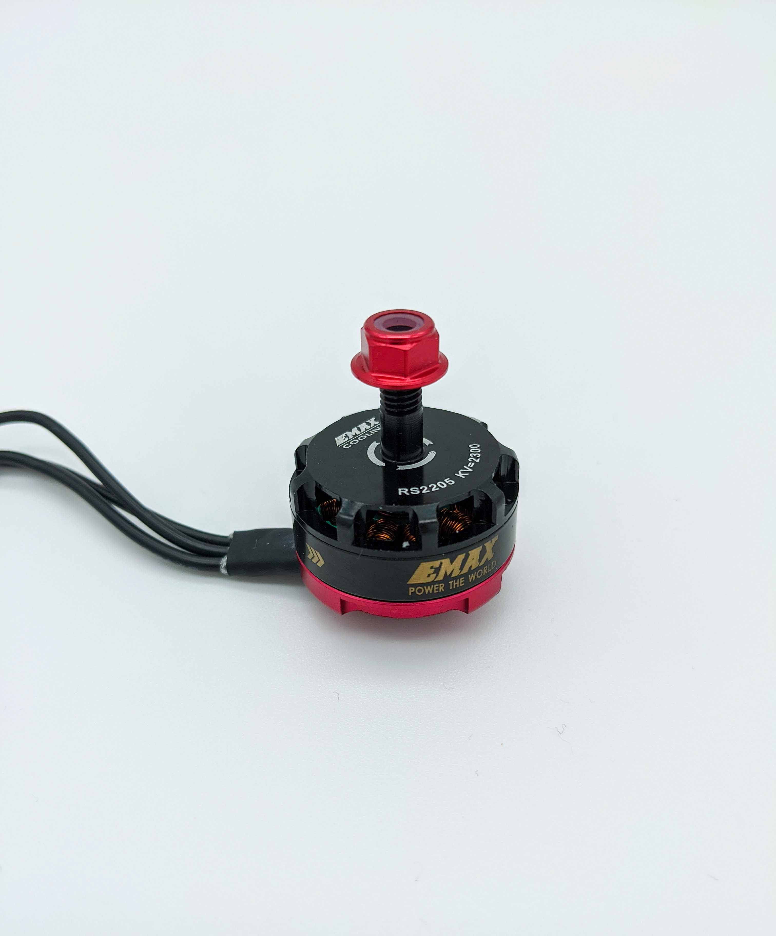
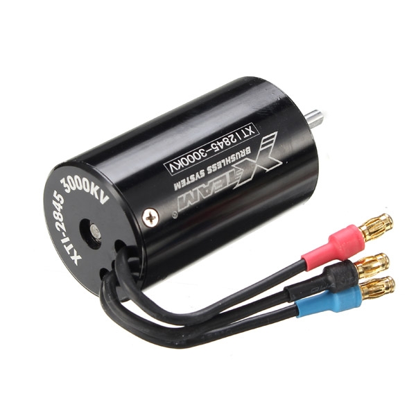
When selecting brushless dc motors for a quad the metrics of the motor, such as its dimensions, configuration and $K_v$ ratings are important. Here we see descriptions such as RS2208 and 12N14P. To select the right motor it is crucial to know what these figures mean.
Velocity Constant
One important constant of a motor is the velocity constant $K_v$ (not to be confused with kV, the symbol for kilovolt) also known as back EMF constant. The constant is measured in revolutions per minute (RPM) per volt or radians per volt second [rad/(V⋅s)]:
\[K_v = \frac{\omega_{\text{no_load}}}{V_{\text{Peak}}}\]The $K_{v}$ rating of a brushless motor is the ratio of the motor’s unloaded rotational speed (measured in RPM) to the peak (not RMS) voltage on the wires connected to the coils (the back EMF). For example, an unloaded motor of $K_{v}=2.300\text{rpm}/\text{V}$ supplied with 10.0 V will run at a nominal speed of 23.000 rpm (2.300 rpm/V × 10.0 V)[ref].
A high $K_v$ rating doesn’t mean that the motor has more power. Instead, the higher the $K_v$ rating, the faster the motor spins with the same voltage applied. However, the faster it spins the less torque it can generate, which leads to a slower rotation with a mounted propeller. One major reason for this behavior lies within the motor configuration, explained below.
Note that the $K_v$ rating is a measured without load and therefore without mounted propeller (idle state).
Dimensions
A description similar to RS2205 describes the dimension of a motor to compare it to other models.
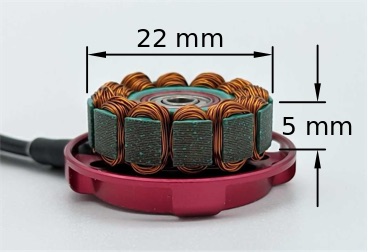
The first two characters show the motor series followed by the dimensions of a stator that’s inside an outrunner. In the table below are two examples
| Motor Description | OEM | Motor Series | Dimensions | Stator Diameter (mm) | Stator Height (mm) | $K_v$ rating (rpm/V) |
|---|---|---|---|---|---|---|
| EMAX RS2205/2300Kv | EMAX | RS | 2205 | 22 | 05 | 2300 |
| Lumenier RX2206-13 2000Kv Motor | Lumenier | RX | 2206 | 22 | 06 | 2000 |
The 13 in the motor description of the Lumenier model describes the number of windings around each .
Motor Configuration
Another important metric describing the inner structure of a brushless motor is its motor configuration, also known as framework. For example 12N14P, where N denotes the number of stator “wire wound” poles and P denotes the number of rotor “permanent magnet” poles[ref].
A magnet always has a north and a south pole. The magnets inside the rotor bell are attached in alternating polarity and therefore attract and repel each other. This generates an alternating magnetic field and is the reason why only an even number of magnets can to construct a brushless dc motor. The stator consists of multiple armatures with copper windings. The armatures of the stator are also known as grooves or stator poles.
How often the copper wire is wound around the stator poles is known as windings or turns. As mentioned, a brushless dc motor has three phase wires because of the 120 degree phase shifted polarity of the current running through those wires. The copper windings act as a electromagnet when current flows through them. Because the dc motor operates with three phase electric power, its number of stator poles (N) is always divisible by three. For example, a 12N14P motor has always four windings that represent one stator pole. A 9N12P has twelve magnets attached to the rotor and nine stator poles with copper windings.
Winding Scheme
Different winding schemes exist, which describe how to wind the copper wires around the stator poles. The most common winding scheme for outrunners is dLRK.
Thrust and Power
The magnets inside the rotor (poles) are always shifted (rotated) from one stator pole (armature) to the next. The more poles (P) and armatures (N) a motor has, the shorter is the distance between these two sections. This leads to a slower spinning motor and therefore a lower $K_v$ rating. The torque on the other hand will be increased. Intuitively this is the force that pulls the rotor magnets from one current carrying armature to the next.
Slower spinning brushless dc motors are output more torque and are more efficient than fast spinning ones. A slow spinning but large propeller is a more effeicient system than a fas spinning motor witha a small propeller attached.
Thrust is often measured grams and varies on how fast the motor is spinning and the size and shape of the attached propeller.
The next two metrics are also important for the thrust output of a brushless dc motor.
Operating Voltage and Current Draw
Two important metrics of a brushless dc are its operating voltage range $U$ and its maximum current drain $I$. These two parameters influence the thrust output. The maximum operating voltage that is allowed to be applied to a motor is often given in Volts (V) or the number cells of battery pack. For example, specifications such as 11.1 Volts or 3S are common. Operating such a motor with 4S or more would cause damage. Using less voltage would work but wouldn’t allow to use the motor’s full potential. Another important specification from the manufacturer is the maximum current drain given in Ampere (A). For a short time period of 60 to 180 seconds a motor will be capable of handling a higher current drain which will be specified by the manufacturer. With the two values (long term current drain and operating voltage) it is directly possible to calculate the maximum power $P$ consumption of the motor in Watt (W). This metric can be used to compare motors and to calculate the thrust.
\[P = U \cdot I\]Motor Weight
The weith of a motor plays a significant role not only to calculate the total weight of a copter, it also influences the maximum possible thrust and flight characteristics. A heavier motor has a higher inertia that leads to less acceleration but higher top speeds. On the other hand, lighter motors will provide higher acceleration and are useful for fast turns and easier to handle when doing acrobatic flips. Which motor weight to choose depends therefore on the intended purpose.
Relation between Thrust and Weight
The thrust specifications are dependening on the used propeller and the applied voltage. Such relations are usually provided from the manufacturer. The following table shows such an example of the EMAX RS2205/2300 $K_v$.
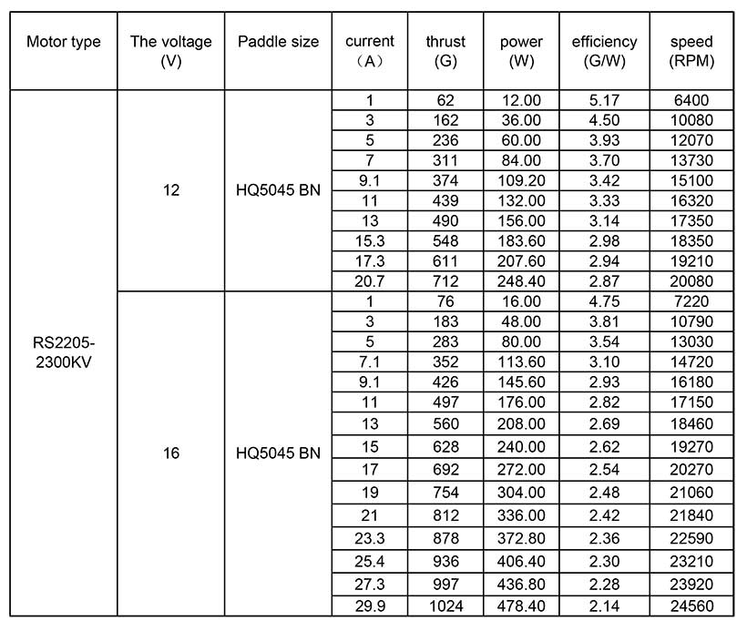
This table also helps to choose appropriate propellers.
Mounting and Rotation Direction
Further reading material
- All About Multirotor Drone FPV Motors at GetFPV learning pages
- Make your own miniature electric hub motor
- Brushless DC Motor Fundamentals
- Common Winding Schemes
Comments